
Older Meetings Archive
April 21 2016 Meeting with Henry Ott

Henry Ott
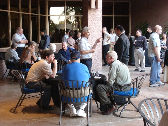
The second meeting in 2016 of the Phoenix IEEE EMC Chapter was on Thursday April 21st 2016 at Compliance Testing Labs. The chapter thanks them for providing their conference room and facilities for this event.
After socializing for a bit, our group of 50+ attendees had an Italian feast of lasagna, penne alfredo, and salad catered from Floridino’s in Chandler.
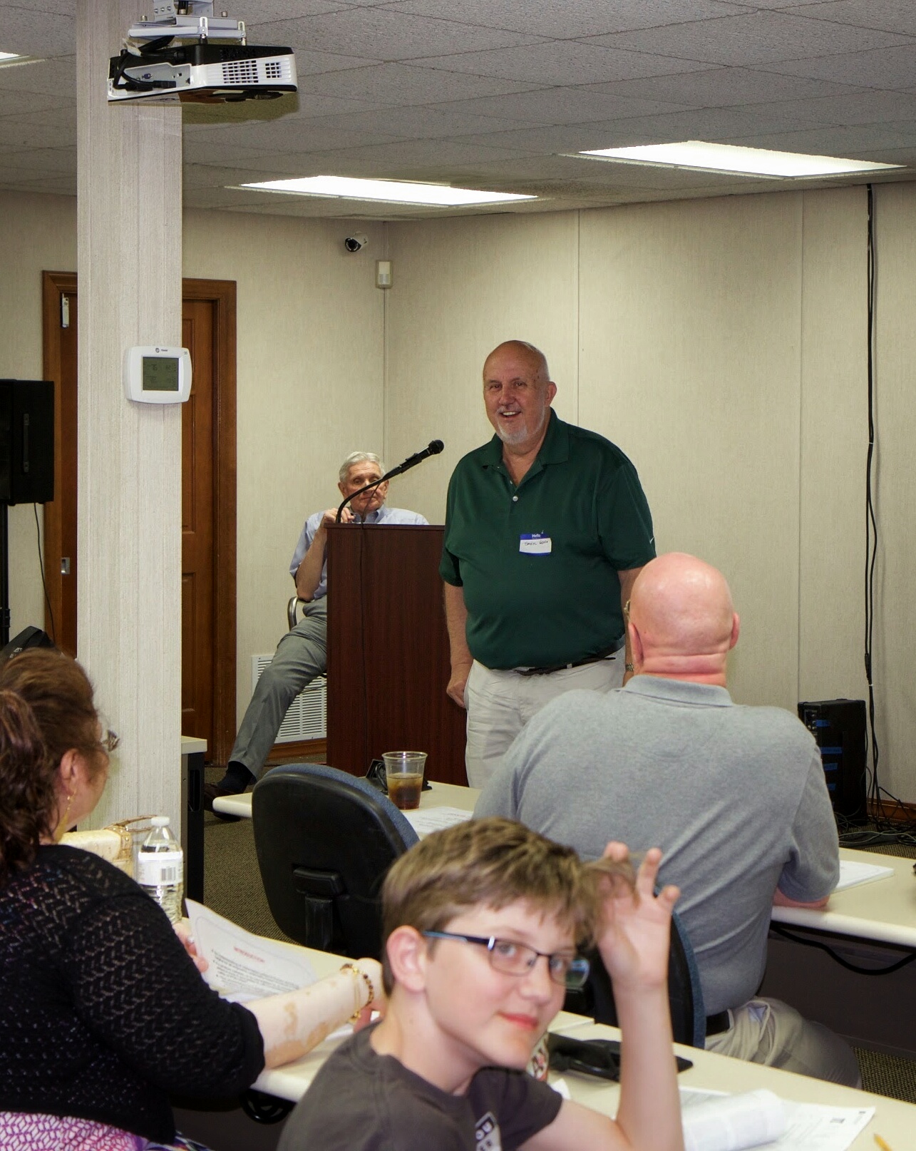
Daryl Introducing Henry Ott
Daryl Gerke, now deemed our chapter’s Vice-Chair and “Godfather” began the meeting with an announcement of proposed new officers for the chapter. After a unanimous vote, Glen Gassaway is now the chapter Chairman, relieving Brett Gassaway who will continue to serve as Vice-Chair. Greg Wilkins was elected the Chapter Secretary and Amanda Reed was elected our Treasurer.
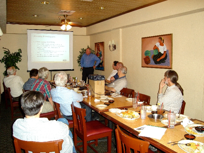
Glen continued the meeting with our customary roundtable introductions and employment opportunities. He then explained to
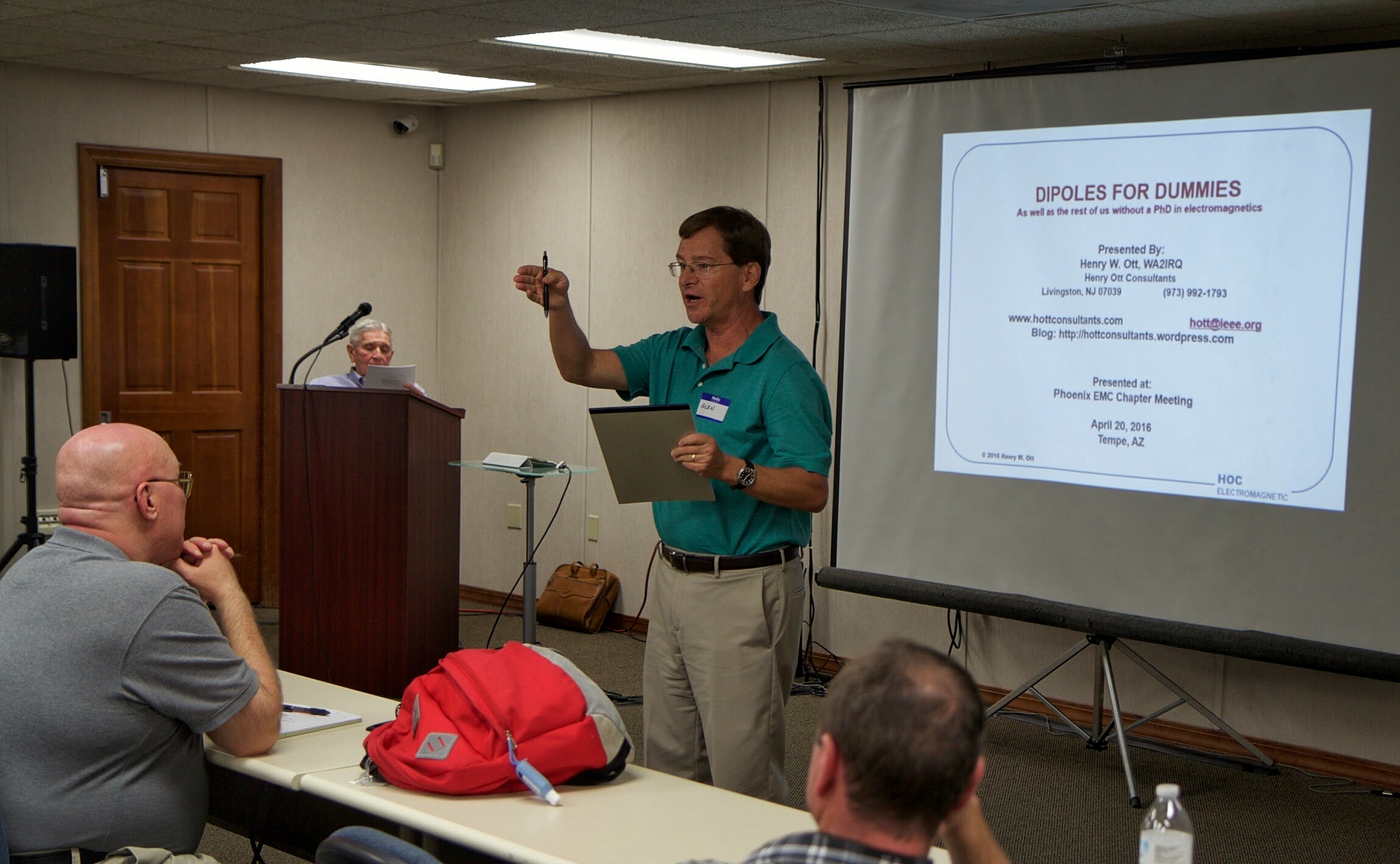
Glen Talking Chapter Business
visitors the advantages of becoming an IEEE member, such as networking opportunities and the search engine for technical papers often not found any other way. In the future, the chapter plans on reaching out to schools and students. Early planning for a mini symposium is also in the works, so stay tuned!
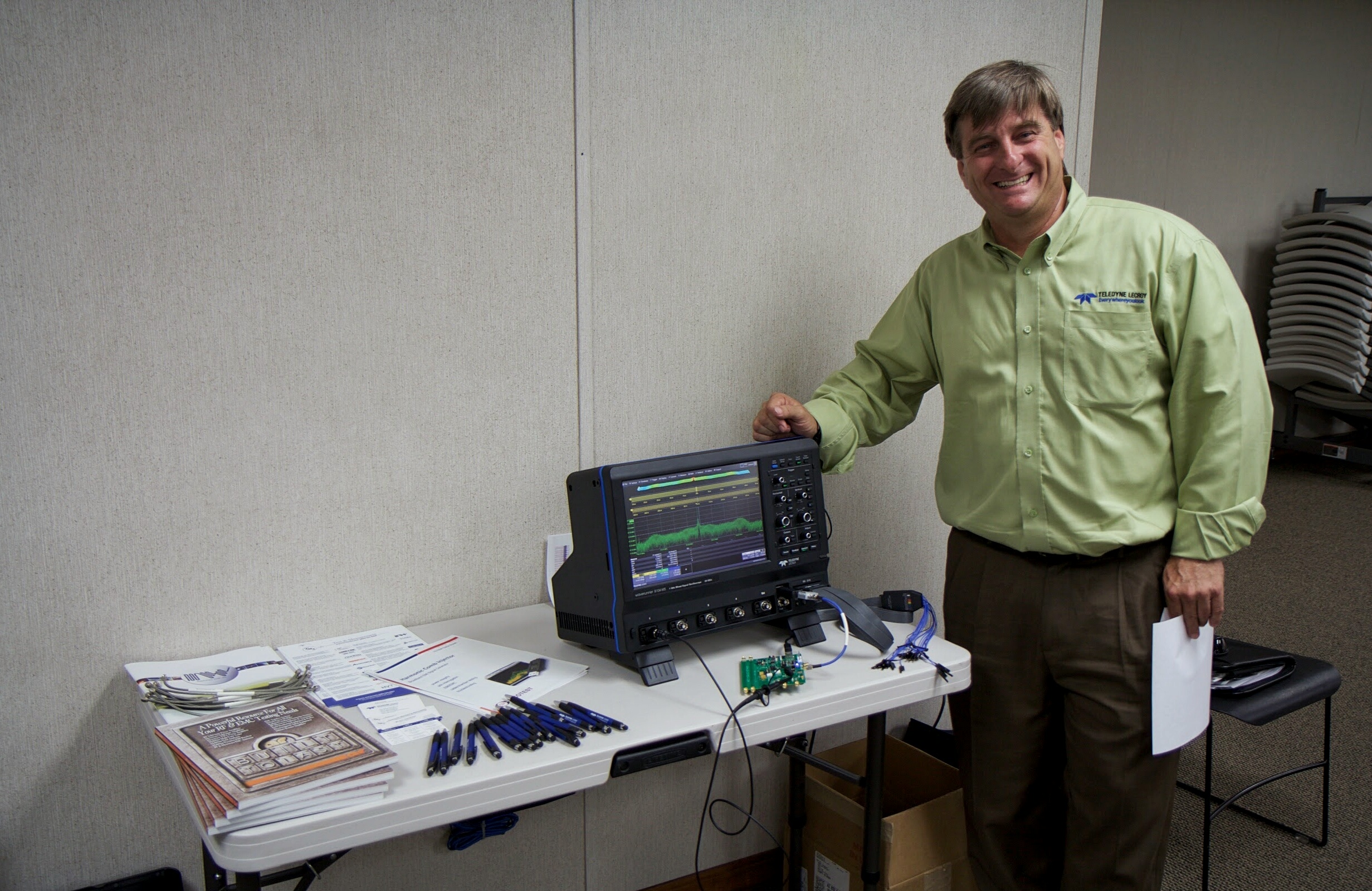
Brent Treadway of TMS showing off a New Anritsu Scope and a Comb Generator
Brent Treadway from TMS was gracious enough to provide beverages for the social hour and also gave a demonstration of new comb generator device to troubleshoot EMC issues at the PCB level.
Our guest speaker was the esteemed Henry Ott, President and Principal Consultant of Henry Ott Consultants, an EMC training and consulting organization.
Prior to starting his own consulting company, Henry was with AT&T Bell Laboratories (currently Alcatel-Lucent), Whippany, NJ, for 30 years, where he was a Distinguished Member of the Technical Staff. He is the author of two books, Electromagnetic Compatibility Engineering (Wiley 2009) and Noise Reduction Techniques in Electronic Systems, (Wiley 1976 and 1988).

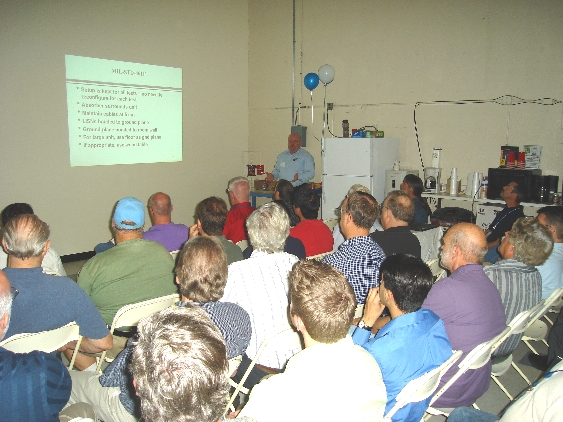
A Packed House Listening to Henry Ott
Mr. Ott is a Life Fellow of the IEEE and an Honorary Life Member of the IEEE EMC Society. For over twenty years, Mr. Ott has served the EMC Society in various capacities including membership on the Board of Directors, Education Committee Chairman, Symposium Committee Chairman and Vice President of Conferences. He is also a member of the ESD Association and holds an amateur radio operator’s license with the call sign WA2IRQ.
Mr. Ott’s presentation was titled “Dipoles for Dummies (as well as all the rest of us without a PhD in electromagnetics)”. It was organized in a four-part series including basic, intermediate, advanced and post graduate levels.
These sections explained by Mr. Ott highlighted the following:
- A dipole antenna requires two parts.
- The magnitude of the radiation will be proportional to the dipole current.
- A dipole antenna does not require a ground to work.
- A monopole is just a dipole in disguise, and also requires two parts.
- The way to make a dipole antenna radiate is to have an RF potential between two pieces of metal.
- The way to prevent radiation is not to have a potential difference between the two halves of the antenna.
- The internal circuit reference (ground) of a product should be connected to the chassis as close to where external cables terminates as possible.
- The polarization of an antenna represents the orientation of the electric field produced by the antenna.
- The effective height of an antenna is defined as the ratio of the voltage induced into the antenna to the magnitude of the incident electric field.
- Adding metal (capacitance) to the end(s) of a dipole or monopole antenna will increase their radiation efficiency
- A PCB should be mounted as close to a metal chassis as possible, and have its ground connected directly to the chassis.
- A plastic enclosure should include a metal reference plane.
- The equivalent circuit of a dipole (or monopole) is a series R-L-C circuit.
- At its resonant frequency, it is much easier to couple energy into an antenna and, therefore, it will be a more efficient radiator at its resonant frequency.
- Antenna resonance will occur when each arm of the antenna is one-quarter wavelength long.
- Multiple resonances will occur that are odd numbered harmonics of the resonant frequency.
- A monopole and dipole both radiate the same field.
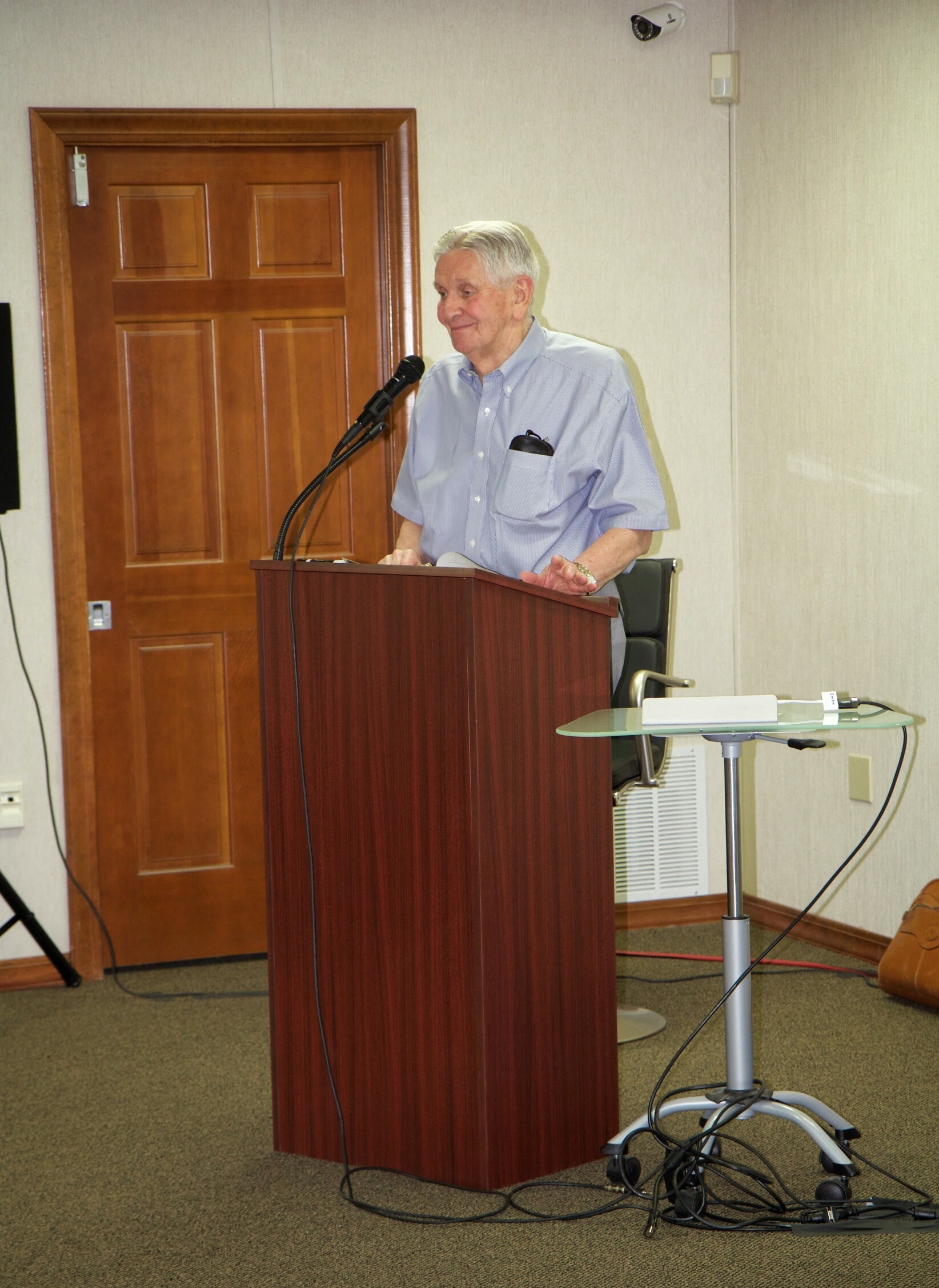
Henry Presenting “Dipoles for Dummies”
The post graduate portion of the presentation covered different antenna types and those suitable for EMC testing. For more information and a white paper Dipoles for Dummies, you can visit: http://www.hottconsultants.com/tips.html
After the presentation, Daryl presented Henry with a copy of Arizona Highways magazine and a jar of scrumptious prickly pear salsa.
This was the last scheduled meeting of the 2015-2016 season. Thanks for all that attended and see you in the Fall!
Thanks to Brett Gassaway and Steve and Michael Schaffer for once again providing the meeting venue at Compliance Labs!
See all event photos here.
February 25 2016 meeting with Bob Scully
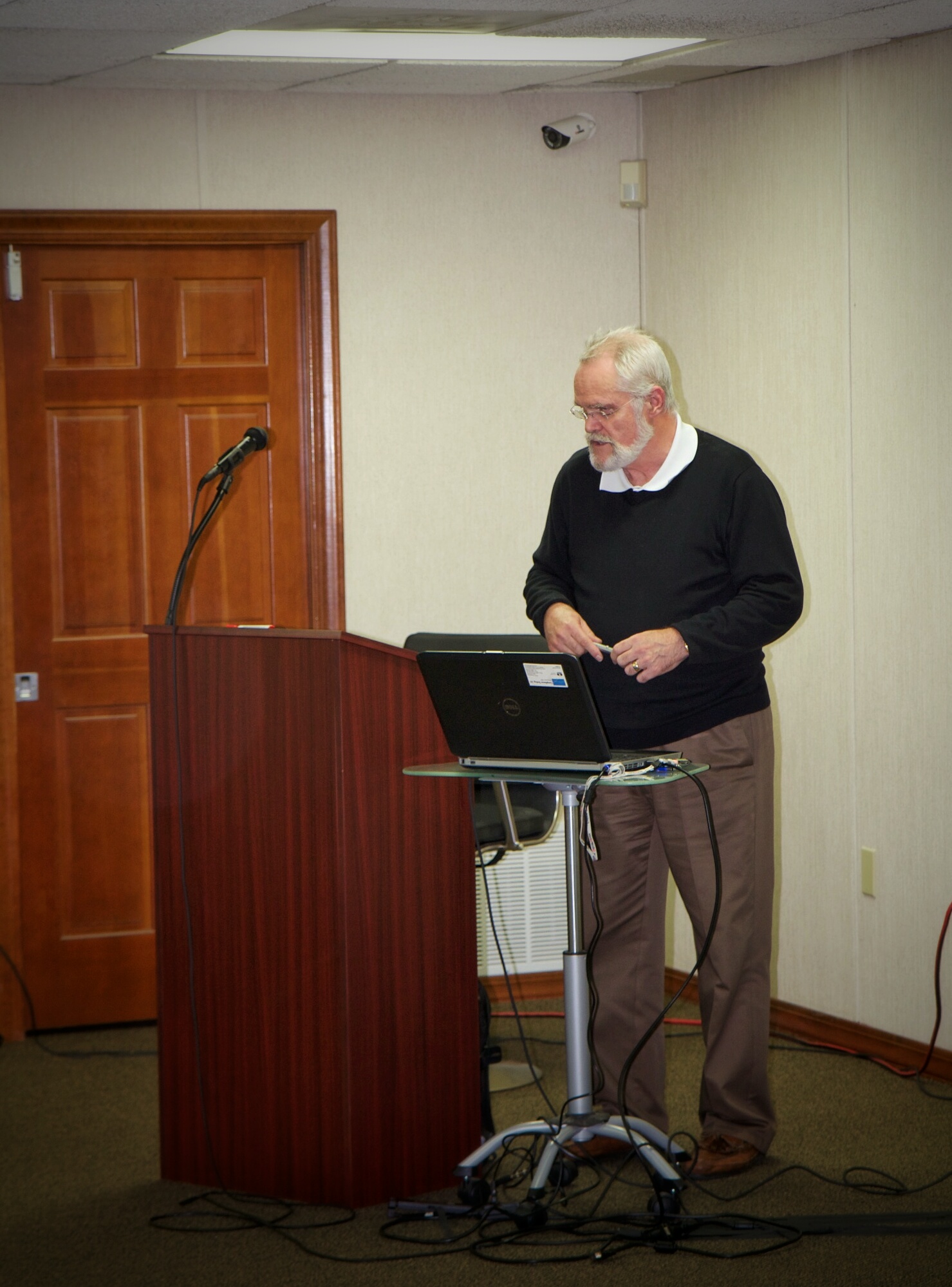
Dr. Scully speaking at our meeting.
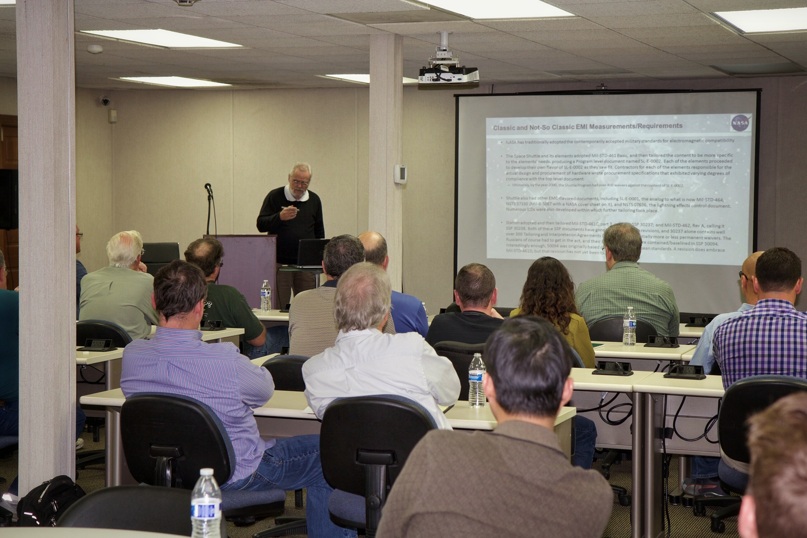
It was a full house, with over 30 members attending!

Super Interesting Presentation
— all photos by Steve Schafer of EMC Compliance Labs
To see more photos of our February 2016 meeting, please click here!
The first meeting of the IEEE EMC Society Phoenix Chapter in 2016 was held on Thursday, February 25th at Compliance Testing Labs at 1724 S. Nevada Way in Mesa, AZ. We had over 32 people in attendance, with many new faces present.
We were honored to have Dr. Bob Scully, the NASA Johnson Space Center Electromagnetics Compatibility (EMC) Group Lead Engineer and immediate past-president of the EMC Society as our Speaker.
After some socializing at 5pm and a hearty meal of Barro’s Pizza & Salad, Chapter Chair Brett Gassaway gave announcements about upcoming meetings and events. Our usual around-the-room introductions were made and information was shared about possible job openings in the Valley.
Glen Gassaway then introduced Dr. Scully at 6pm.
Dr. Scully is the NASA Johnson Space Center Electromagnetics Compatibility (EMC) Group Lead Engineer, serving as the technical lead for EMC at the JSC. He supports NASA’s major programs including the International Space Station, the Multi-Purpose Crew Vehicle and the Commercial Crew Development Program. Bob is currently serving as the Immediate Past President of the EMC Society as well as the Chair of the Galveston Bay/Houston EMC Chapter. He is a Professional Engineer in the state of Texas, a licensed commercial and amateur radio operator, holds various EMC certifications from the University of Missouri at Rolla and iNARTE.
Dr. Scully expressed how classic MIL-STD-461 style conducted and radiated measurements have been adapted and tailored for use by NASA JSC programs. For instance, the Space Shuttle program developed SL-E-0002 and each element of that program developed a flavor of SL-E-0002 as they saw fit. The ISS adopted and tailored MIL-STD-461C and MIL-STD-462, calling them SSP 30237 and 30238, respectively. The Orion program and its counterparts (SLS and GSDO) each have their own separate version of EMC requirements that exhibit features unique to each of their programs and incorporate commercial requirements. There is a recurring theme: Space EMI specifications are highly tailored and commercial requirements are here to stay!
Dr. Scully presented a humorous yet all-too-familiar comic strip describing how standards proliferate. The baseline situation is that there are “14” competing standards describing some technical requirement. Two engineers then say “14? Ridiculous! We need to develop one universal standard that covers everyone’s use cases”. The next frame states that there are now 15 different standards!!! Those of us on standards committees know this situation a little too well.
Dr. Scully then shifted gears and described the RF environments for launch vehicle ground handling, launch, orbit, and descent. He compared the Space Environment given in MIL-STD-464C to the defined RF environments for Orion (including Launch, On-Orbit and Near ISS). The result? 464C covers many of the larger emitters but not all. It’s vitally important to be aware of your actual and specified environment!
Dr. Scully also discussed the space plasma environment in both LEO and GEO, detailing the charging threat and the resulting ESD effects. He played a very interesting video taken from the ISS, showing aurora and other plasma effects. He defined the differences in ion/electron energies in LEO versus GEO, and what would be needed to protect against these environments. He showed images of Solar Array panels that were damaged by arc discharge and how a Plasma Contactor is used on the ISS to mitigate charging effects.
Finally, Dr. Scully gave an extremely interesting presentation of lightning effects on space vehicles. Lightning must be considered during the transportation, prelaunch and launch phase of the mission. Lightning risk calculations are not perfect, and it is not reasonable to expect them to be so. According the KSC weather office, even with all of the lightning constraints in place on the eastern range, there is a 10-3 to 10-4 chance of a lightning strike during ascent. Bob showed several photos of nearby and direct launch vehicle strikes that have occurred in the past, including one of the two separate bolts that struck Apollo 12 on several seconds after liftoff! He also showed an extremely interesting video of the “Birth of a Lightning Bolt’ using a very high speed camera in order to demonstrate the stages of lightning development. He talked about how to determine the magnitude of indirect effects, how lightning E&H fields may penetrate conducting materials, coupling mechanisms and mitigation measures.
Chapter chair Brent Gassaway took the floor to close the meeting and to mention that we have several exciting activities in the planning stage, with at least one speaker in April with more in the ‘works’. We also have factory and lab tours in the planning stages for this summer.
After the meeting, several folks mentioned that Dr. Scully’s presentation was very interesting and entertaining. Thanks to Dr. Scully to make the trip from Houston and thanks to all who attended!
December 10, 2015 meeting with Daryl Gerke

Daryl Gerke of Kimmel Gerke Associates speaking at our December 10 meeting
Greetings and Happy Holidays, EMC’rs! The last Phoenix IEEE EMC Chapter meeting of the year was held on Dec 10th. Twenty-eight people were in attendance, with some new faces present.
After some socializing at 5pm and a hearty meal of Rubio’s Mexican food at 6pm, Glen Gassaway gave an introduction and explained what the IEEE EMC chapter was all about. He made announcements about the new website and membership. Our usual around the room introduction was made and information was shared about possible job openings at General Dynamics, Microchip, and UTC Aerospace.
The guest speaker was our very own Daryl Gerke. Daryl has been involved with EMI/EMC issues for over 45 years. He is a cofounder of Kimmel Gerke Associates, an EMI/EMC consulting/training firm. He has a BSEE from the University of Nebraska, is a Registered Professional Engineer (PE), and an iNARTE Certified EMC Engineer. Daryl resides in Mesa, Arizona, unless he is in Minnesota escaping the summer heat.
Daryl began the presentation by defining what the requirements and goals of a PC design review are. Advantages include saving time and money early on in the design stage. He highlighted that it makes sense to base EMC design fixes based on risk. An “ABC” list of items, “A” being the easiest to implement and “C” being the most costly or difficult to implement is a good methodology. You can always remove fixes if you don’t need them, but it may be difficult to implement them after the fact. This again can be time consuming, costly, and reduce market share.
Daryl then went on to explain the top 10 things to look at when performing a design review and how they can be affected by poor EMI design. He also provided a board level design review checklist.
1) Clock Circuits
- Vcc- decoupling cap (optional ferrite)
- Clock out-Series resistor
2) Reset/Interrupt/Control Circuits
- Vcc-decoupling cap
- Inputs-high frequency filtering
- Serious filtering on external reset inputs
- Outputs-high frequency filtering as needed
3) Analog Circuits
- Vcc-high frequency decoupling
- Inputs (including reference)-high frequency filtering
- Optional small cap across the input
- Outputs-high frequency filtering as needed
4) Voltage Regulators
- 1000pF caps at input and output to neutral pin
5) RF Transmitters and Receivers
- Receiver inputs-keep noisy circuits/traces/cables separated
- Frequency management of clocks
- Shilding (modules common)
6) Board Stackup
- Every trace layer adjacent to a plane
- Planes are paired
- High speed traces buried
7) Split Planes
- No traces across cuts
- No overlapping planes
8) Floor Planning and Trace Routing
- Components grouped by function/speed
- Critical traces routed to minimize EMI
- No clocks/resets adjacent to I/O
9) I/O and Power
- Filters and bandwidth on I/O
- High frequency capacitor on power
- Transient protection as needed
10) PCB Grounding
- I/O chassis grounding at connectors
- Multi-point connections for high frequency boards
- Hybrid or single point connections for low frequency boards
In conclusion, Daryl added, “Grab a buddy for your review as two heads are better than one!” Glen presented Daryl with a jar of Arizona’s infamous Prickly Pear Jelly as a token of our appreciation.
Thanks for all who attended and check back soon to see when the next meeting is scheduled!
On September 10, 2015, the IEEE Phoenix EMC Chapter hosted a table top exhibit at the “EMCmini” symposium at Compliance Testing Labs. EMCmini is an on-going, commercial, non-IEEE-sponsored event. Our chapter was in full support of this interesting workshop targeted to beginning EMC engineers. Four EMC experts spoke at the mini-symposium, covering regulatory standards, design for EMC, PCB layout concepts and much more. Approximately 15 EMC vendors were also in attendance. After the symposium, Compliance Testing gave lab tours and an energetic social hour was sponsored by the vendors. We appreciate that we were able to be a part of the show!

It was a crowded house at the EMC-Mini symposium

Ghery Pettit gives a presentation on EMC rules and regulations at EMC-Mini
For many more pictures of the EMC-Mini symposium, click here! . Thanks to Steve Schafer of Compliance Testing Labs for being the official photographer!
In May 2015, several volunteers from the Phoenix IEEE EMC Chapter supported the International Microwave Symposium (IMS) 2015 held in Phoenix, Arizona from May 18-21. The IEEE EMC Society is entering a new cooperative arrangement with both the IEEE Antennas and Propagation Society and the IEEE Microwave Theory and Techniques Society, which gives us the unique opportunity to align ourselves with our closely related societies. As a result, members of the Phoenix Chapter were called upon to help hand out flyers, membership applications, staff a booth and generally provide information about the EMC Society during the symposium. At the symposium, we also showed off a few EMC ‘magic-tricks’ by giving on-going demonstrations of field-to-wire coupling and basic shielding theory. They were a real hit – especially with the STEM junior high and high school students that were on field trips. Our demos also seemed to make an impression on some of the ‘bigger kids’ too! All in all, it was an interesting and rewarding experience for our Chapter volunteers. PS: IMS 2016 is in San Francisco
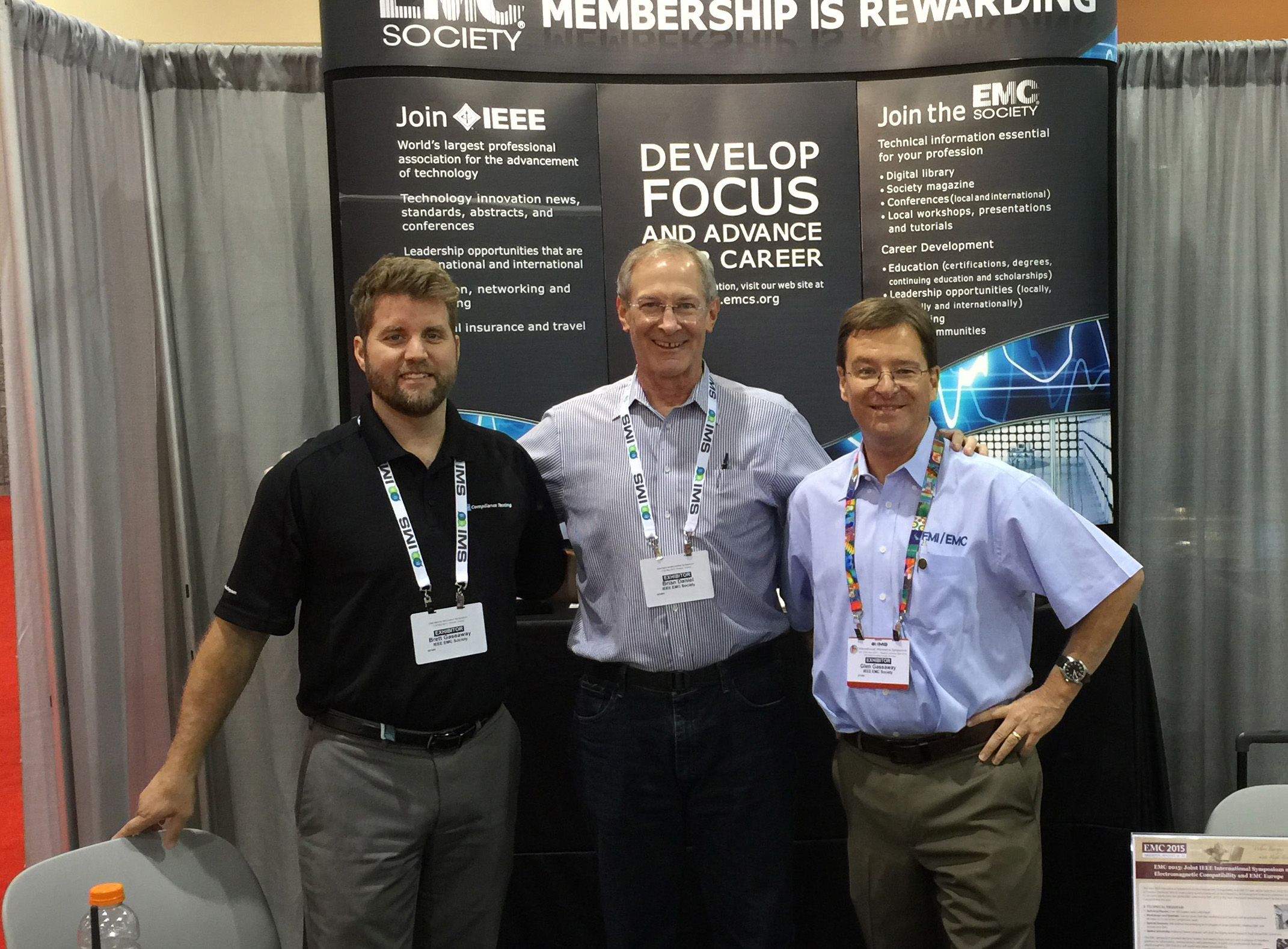
Manning the IEEE EMC Chapter booth at the IMS. From left to right, Brett Gassaway (Compliance Testing Labs), Brian Daniel (OrbitalATK) and Glen Gassaway (Southwest EMI Consulting).
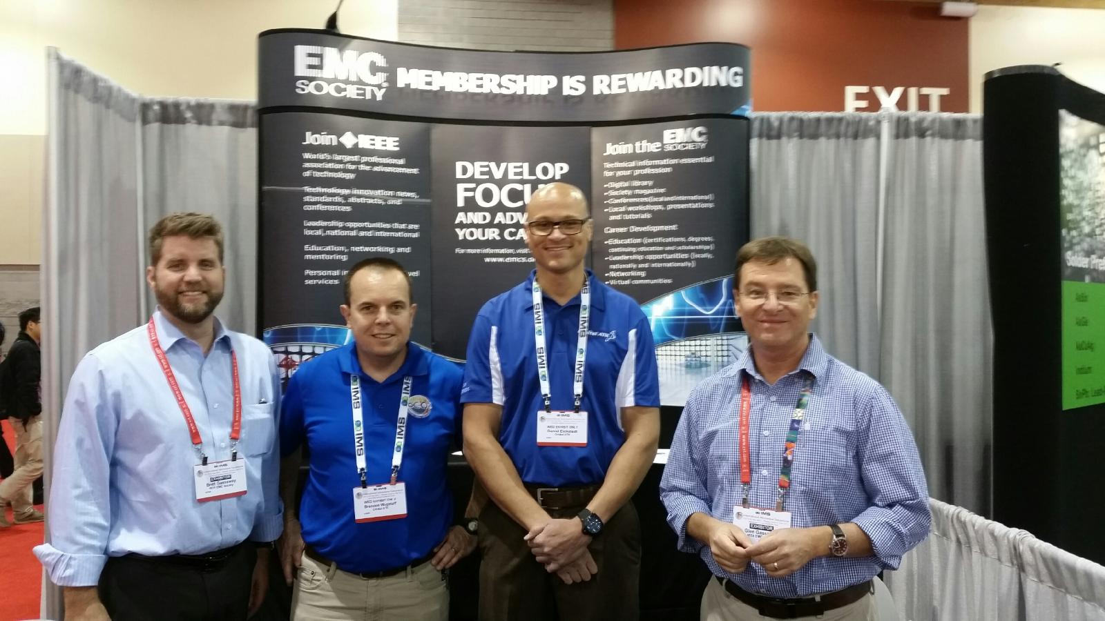
Manning the IEEE EMC booth at the IMS. From left to right, Brett Gassaway, Brandon Wagstaff and Danny Eickstadt (both with OrbitalATK) and Glen Gassaway.
The Phoenix EMC/MTT/AP Joint Chapter held a half-day workshop titled, “New EMC Measurement Techniques for Efficient and Compliant Antenna Calibration and Test Site Validation” on February 25, 2015. The workshop was hosted by Compliance Testing, LLC in Mesa, AZ. EMC Chapter officers Brett Gassaway of Compliance Testing, Glen Gassaway of Southwest EMI and Daryl Gerke of Kimmel Gerke Associates organized the event. After a delicious complimentary buffet lunch, some 40 Chapter members and guests settled into their seats for an interesting technical program.
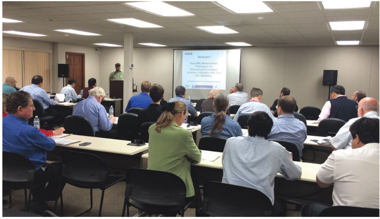
Brett Gassaway welcomes the attendees at the start of the technical workshop
The first speaker was Doug Kramer with ETS Lindgren. He provided a one hour presentation titled, “Introduction to Antenna Calibration Methods: An overview of new antenna developments, related standards, calibration and what you need to know for efficient and compliant EMC testing.” Doug provided an overview on antenna calibration, what it means to calibrate an antenna and why it’s important to your test measurement set up. The set of operations for an antenna calibration that establish the relationship between values of quantities indicated by a measuring instrument and a reference standard were explained. Essential concepts were reviewed, such as metrology, verification, validation, and accreditation. Case studies were provided on these concepts to provide practical examples of the concepts as applicable in the real-world. Finally, traceability and measurement uncertainty were addressed according to standards such as ANSI C63.5, SAE ERP 958, IEEE 291, and CISPR 16-1-6. The presentation concluded with a review of new antenna developments, including tips on which antenna to use for what measurement application, trade-offs in evaluating different antennas, and the new “balance test” for biconilog antennas. The second speaker was Zhong Chen with ETS-Lindgren. Zhong provided a one hour presentation titled, “CISPR sVSWR versus ANSI C63® Time Domain sVSWR: A review of current and future measurement techniques for faster and more accurate test site validation.” His presentation reviewed the recent advances in the theory and measurement of the time domain site VSWR (TD sVSWR) method. The test setup of the TD sVSWR method resembles those included in the CISPR sVSWR method, including the antenna height, locations, and polarizations. Zhong explained how the TD sVSWR method obviates the need to move the antennas to six positions along a 40 cm line. Instead, it uses the time domain transformation of the frequency domain data to separate the direct antenna response from the reflections in a chamber. The sVSWR can then be calculated from that data. He provided data on recent measurements that document the TD sVSWR method results are closely correlated to the CISPR sVSWR method results. Background information on the development of the method was presented, as well as actual data collected from several EMC commercial test labs showing the sVSWR using both the time domain and the CISPR methods. Extensive data analyses were also presented that showed the benefits of the TD sVSWR method, including faster testing (1/6th of the test time), better repeatability, greater accuracy in determining defects, and lower measurement uncertainties. Zhong noted the TD sVSWR method is expected to be included in the latest draft version of the ANSI C63.25 standard on test site validation. He is active in helping to write that standard as a member of the ANSI C63.25 working group.
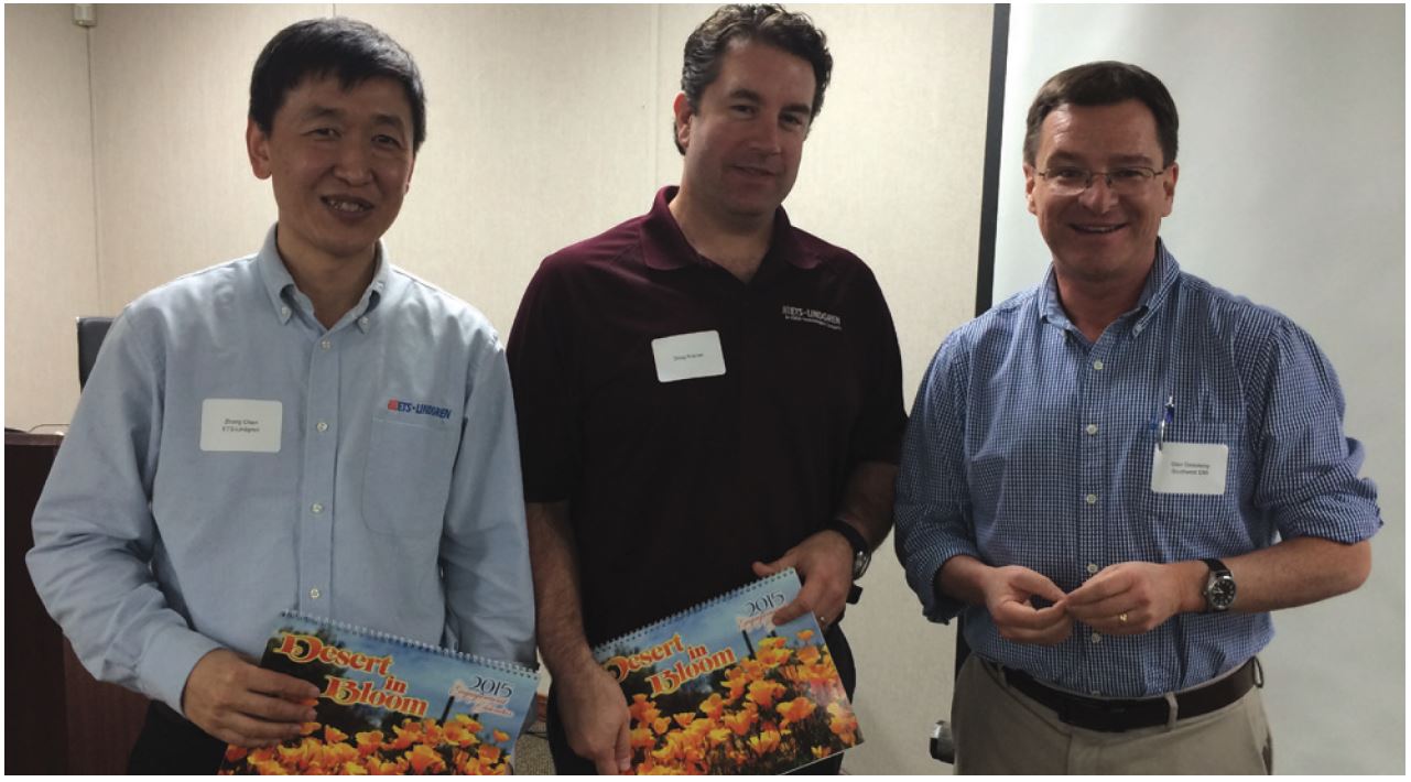
Glen Gassaway presents Zhong Chen and Doug Kramer with Arizona calendars as a token of appreciation from the Phoenix Chapter

Doug Cramer and Zhong Chen demonstrate the time domain VSWR measurement concept in Compliance Testing Lab’s main chamber
A highlight of the workshop was the facility tour and hands-on demonstrations that followed the presentations in the semi-anechoic EMC chamber at Compliance Testing. These provided a real-world example of the material presented and further enhanced the understanding of the time domain measurement technique. Many attendees stayed past the conclusion of the workshop to see different variations of the demonstration and to discuss the data collected. The test lab at Compliance Testing was impressive with several chambers available for different types of testing. It also had a lot of space to get things done by the friendly and capable personnel present. Keysight Technologies loaned a new PNA analyzer that performed to 26.5 GHz and included the time domain software upgrade. Talk about impressive equipment! Attendees appreciated seeing how efficiently this instrumentation handled the time domain measurements. The Phoenix EMC Chapter officers wish to thank Compliance Testing LLC for their generous support in hosting the workshop and Keysight Technologies for loaning the PNA instrumentation for the demonstrations. Special thanks to Michael and Steve Schafer of Compliance Testing and Rebecca Suemnicht of Keysight Technologies whose collective efforts were a HUGE contribution to the success of the workshop. Doug is the Manager of the Calibration/EMC/ Wireless Labs for ETS-Lindgren in Cedar Park, Texas. He has over 12 years of experience in managing a commercial test laboratory and providing test solutions to a variety of customers. He holds BSEE and MSEE degrees in Electrical Engineering from the University of Nebraska-Lincoln and is the outgoing Chair of TC1 of the IEEE EMC Society. Doug supports the technical staff at ETS-Lindgren, many of whom are active contributors to the leading wireless industry organizations, including the CTIA – The Wireless Association®, 3GPP, and the Wi-Fi Alliance®. Prior to joining ETS-Lindgren, Doug was the General Manager for the Nebraska Center for Excellence in Electronics (NCEE), the only full service EMC, environmental and safety product testing facility in Nebraska. He is a contract Senior Assessor to ISO/IEC 17025 and is an iNARTE certified EMC Engineer, a member of the CISPR B working group and Vice Chair of the ANSI C63.5 working group. Zhong Chen is the Director of RF Engineering at ETS-Lindgren, located in Cedar Park, Texas. He has more than 19 years of experience in RF testing as well as EMC antenna and field probe design and measurements. He is an active member of the ANSI ASC C63® parent committee and chairman of its Subcommittee 1 which is responsible for the antenna calibration and test site validation standards, including ANSI C63.4, C63.5 and the new C63.25. He is chairman of the IEEE 1309 committee for developing calibration standards for field probes. Zhong Chen received his M.S.E.E. degree in electromagnetics from the Ohio State University at Columbus. He may be reached at zhong. chen@ets-lindgren.com.

Steve Schafer and his team were instrumental in making sure the workshop ran smoothly!
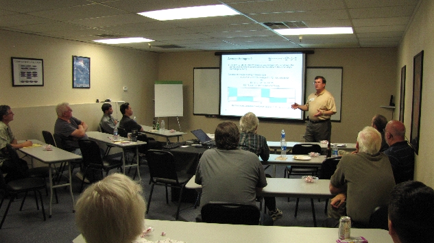
Harry Gaul reports the IEEE EMC Phoenix Chapter met on September 7th, 2013 at Garcia’s Mexican Restaurant in the Embassy Suites Hotel in Tempe, AZ. Our speaker for the evening was Mike Hopkins of Amber Precision Instruments. The topic of his presentation was “New Scanning Tools for EMC Investigations”. Mr. Hopkins explained how hard failures from ESD have evidence such as dead components. But ESD upset effects at the chip and board level are typically secondary effects. Most problems in the fields are subtle “soft” failures such as reset, re-boot, and lockup. These failures can be especially bad in medical and flight critical equipment where no upsets are allowed whatsoever. Mike presented some novel 0.5 mm diameter loops to radiate extremely fast risetime transients onto chips and PCB’s to map out the sensitive components and traces. These new scanning techniques can reduce risk of compliance and can also help pin down the root cause of transient immunity failures when they do occur.
Mike Hopkins explains to the Phoenix Chapter how new scanning tools can be used to identify circuits that are susceptible to ESD and other transients. Photo by Stephen Gerard.
Harry Gaul reports the IEEE EMC Phoenix Chapter met on September 21th, 2012 at Garcia’s Mexican Restaurant in the Embassy Suites Hotel in Tempe, AZ. Our speaker for the evening was Daryl Gerke of Kimmel-Gerke Associates, who is also our Vice-Chair. The topic of his presentation was “Printed Circuit Board EMC Design Reviews”. Mr. Gerke recommend
design reviews be held at the block diagram phase and at the schematic/board artwork stage. There are three key areas to review including critical circuits, board construction, and the board periphery. Clocks can be a primary source of emissions so it is critical to bypass the Vcc line with decoupling caps. A series ferrite bead (100 ohms @ 100MHz) can be inserted upstream of the cap to create a two-pole filter. Mr. Gerke presented ten design tips and liberally peppered them with war stories of what happened when the tips were violated in the past. A copy of Daryl’s handout is available on the Phoenix EMC Chapter’s web site at http://www.site.ieee.org/pheonix-emcs/ Click here to download Daryl Gerke’s presentation handout. 
Daryl Gerke entertains the Phoenix EMC Chapter with an excellent presentation on the recommended approach of doing printed circuit board EMC design reviews. Photo by Stephen Gerard.
The IEEE EMC Phoenix Chapter met on September 20th, 2012 at Garcia’s Mexican Restaurant in the Embassy Suites Hotel in Tempe, AZ. Our speaker for the evening was Harry Gaul, EMC Lab Manager, of General Dynamics C4 Systems. The topic of his presentation was “Electromagnetic Modeling and Measurements of the 104cm Rod and Biconical Antenna for RE102 Radiated Emissions Testing Below 30MHz”. Mr. Gaul investigated a variety of grounding configurations for the active rod antenna by using a Method of Moments modeling tool as well as chamber testing in his EMC lab to determine the optimum approach for grounding the rod antenna’s counterpoise. The bottom line from his presentation is that the counterpoise should have no ground at all! To accomplish this, a commercially available analog fiber optic link is used in place of the typical coax cable. Interestingly enough, the test setup with the highest amount of measurement error is the one from MIL-STD-461F with the ferrite bead on the coax cable. The ferrite bead causes a resonance in the test setup around 25 MHz. Mr. Gaul also presented results of using a biconical antenna in place of a rod antenna from 20 MHz to 30 MHz. He found that the biconical antenna tends to under-measure by as much as 10dB, especially when using the 1m ACF values obtained from the ARP958 calibration method. The next step will be to convince the standards committee to allow the use of a fiber optic coupled rod antenna. This will be a real challenge!

Harry Gaul entertains the Phoenix EMC Chapter with an excellent
presentation on the issues with grounding active rod antennas during
RE102 testing. Photo by Stephen Gerard.
The IEEE EMC Phoenix Chapter met on April 19, 2012 at the NTS facilities on 1155 West 23rd Street, AZ. Many thanks go to NTS for hosting the meeting and for providing drinks. A tour of the testing facilities was also offered by NTS and gave us the chance to learn about their diverse capabilities. Our speaker for the evening was Paul Schwerman, who presented “Inches to the Fifth – The Electrical Way To Design Magnetics”. The formula for designing transformer cores was named “Inches to the Fifth” by Lowell Quist because the dimensional units for
the core (inches) is raised to the fifth power. Mr. Schwerman started with a review of magnetic fundamentals, caveats about Self Resonant Frequency (SRF), tolerances, and life limiters in magnetics. Next, he emphasized why the Inch to the Fifth is a better methodology than the conventional one as it provides for regulation (or dc resistance) to be a free variable in the design process. This regulation based methodology can be applied to both transformers and inductors. Various aspects and constraints of inductor design were discussed with a couple of examples. The presentation concluded with a discussion of production issues for magnetics, such as winding techniques and materials. Our thanks to Mr. Schwerman, to all who attended, and to our host for the evening!
Paul Schwerman explains how to efficiently design inductors to the Phoenix Chapter. Photo by Stephen Gerard.
The IEEE EMC Phoenix Chapter met January 19th, 2012 at Garcia’s Mexican Restaurant in the Embassy Suites Hotel at Rural Road and I-60 in Tempe, AZ. The meeting began with the customary social hour starting at 5:30 pm, with dinner at 6:00. At 6:15, our chapter Chair Harry Gaul called the meeting to order. Before the regular meeting Daryl Gerke of Kimmel Gerke Associates, Ltd. took a couple of minutes to pay homage to the memory of Terry Donohoe, one of our members and former Chairman of the Chapter. He sadly perished in a crash while piloting his experimental aircraft in December. Terry will always be remembered with gratitude for his efforts in re-launching of the Phoenix EMC Chapter in the early 2000’s. He will be sorely missed as a friend and colleague. Our speaker for the evening was David Stanis, Retired General Manager Filter Division of WEMS Electronics. His talk addressed the various types of industry wide custom EMI filters both single circuit components and multi-circuit filter assemblies. Mr. Stanis started by presenting the basic types of filters, their structure and recommended application. The modes of propagation of EMC Noise (Radiated and Conducted) Susceptibility issues they pose and filter type selection to address them were discussed. The difficult task of properly identifying the EMC issue and correct selection of a suitable filter to address it was discussed next. Mr. Stanis emphasized the need to work closely with the filter manufacturer to tap into their extensive knowledge and expertise especially when it comes to size and derating. Involving a knowledgeable team in the design effort at early stages can help identify and solve issues faster and at lower cost. Various aspects of filter specification were presented: topology, voltage and frequency, operating temperature and humidity, housing type and mounting requirements, space constraints, hermetic sealing, etc. The presentation concluded with a discussion of Electrical and Environmental Test methods, Quality Inspection and Data reporting considerations. The meeting was called to a close at about 8:30 pm. Our thanks to Mr. Stanis and to all who attended! 
David Stanis provided valuable information on EMI filters to the Phoenix Chapter. Photo by Stephen Gerard.
The IEEE EMC Phoenix Chapter met November 10th, 2011 at Garcia’s Mexican Restaurant in the Embassy Suites Hotel at Rural Road and I-60 in Tempe, AZ. The meeting began with the customary social hour starting at 5:30 pm, with dinner at 6:00. At 6:15, our chapter Chair Harry Gaul called the meeting to order.
Our speaker for the evening was Alex McEachern of Power Standards Lab. The topic of his Presentation was “Smart Grid and Power Quality”. In a very entertaining and insightful manner, he presented the new challenges posed to the Power Grid by renewable energy power generators (Wind Turbines, Solar Panel Systems, etc.) as well as practical power systems issues he encountered across the world during his distinguished career.
Cleanliness of the available power as well as Grid Stability are becoming of concern as small Electric Power Generators go on and off-line at random while the Grid Management Systems are designed to handle mostly large units. Locally-generated power will become more readily available but will also create new challenges, some of them yet unforeseen.
As distributed power generation is becoming more common everywhere in the world, the need for flexible, reconfigurable grid arises. Phase delays between generators can cause oscillation, reconfiguring the grid can create resonance and harmonics and all these issues have to be dealt with in real-time in order to keep the system stable.
Mr. McEachern also presented the Power Quality Teaching tool software, a free software application available on his company website at:http://www.powerstandards.com/PQTeachingToyIndex.htm
As the Chairman of IEC 61000-4-30 Power Quality Measurement Methods, Alex also made an appeal for contribution to the development of this standard. Measuring noise in the frequency range of 10 – 150 kHz is a topic not currently covered well, neither by existing standards nor by existing measurement and test instrumentation.
The meeting was called to a close at about 8:30 pm. Our thanks to Mr. McEachern for the very informative presentation and to all who attended!
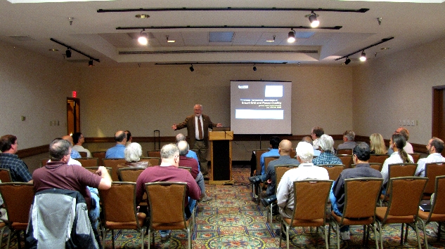
Alex McEachern entertained the Phoenix EMC Chapter with an excellent presentation on the Smart Grid and Power Quality. Photo by Stephen Gerard.
The IEEE EMC Phoenix Chapter met April 14thth, 2011 at Garcia’s Mexican Restaurant in the Embassy Suites Hotel at Rural Road and I-60 in Tempe, AZ. The meeting began with the customary social hour starting at 5:30 pm, with dinner at 6:00. At 6:15, our chapter Chair Harry Gaul called the meeting to order. Details were shared about the EMC symposium in Long Beach. It is scheduled for August 14-19th. You can get an advanced copy of the program on the internet:
http://www.incompliancemag.com/DigEd/emc2011ap-final/index.html. Volunteers are needed so please contact Harry for more details. Our speaker for the evening was Nicholas Wright of HV Technologies who presented the practical impact that advances in technology and transient test standards have on the EMC test lab. His topics included changes to standards and test equipment requirements for induced lightning and voltage spikes including updates to DO-160/ED14, Airbus ABD 0100.1.2G, Airbus ABD0100.1.8G, MIL-STD-461 HEMP requirements, MIL-STD-461 and DO-160 indirect effects of lightning (IEL). Mr. Wright began by defining indirect lightning and breaking it up to 4 fundamental components In the case of an aircraft, indirect lightning is a secondary effect derived from a direct lightning event, such as coupling through apertures, such as windows, aircraft skin and magnetic fields induced into aircraft cables. Nick Discussed the evolution of international standards and the introduction of DO-160 as an international accepted standard for generic LRU level testing. He went on to discuss the series of standardized waveforms used for damage tolerance and immunity tests and highlighted some of the more common waveforms, their origination, and their accepted uses. Nick updated us on the anticipated changes for DO-160G which will add a new hybrid waveform WF6H and proposes to replace section 19 with CS115 to simulate chattering relays. He also updated us on the changes to the Airbus standards ABDO100.1.2 to handle the new composite materials of the A380 aircraft. The meeting was called to a close at about 8:30 pm. Our thanks to Mr. Wright for the very informative presentation and to all who attended!
Nicholas Wright of HV Technologies explains the indirect effects of lightning to the Phoenix EMC Chapter. Photo by Stephen Gerard.
The second IEEE EMC Phoenix Chapter meeting of the 2011 season was held on March 17th, 2011 at Garcia’s Mexican Restaurant in the Embassy Suites Hotel at Rural Road and I-60 in Tempe, AZ. The meeting began with the customary social hour starting at 5:30 pm, with dinner at 6:00. At 6:15, our chapter Vice chairman Darryl Gerke called the meeting to order while we were all enjoying Garcia’s excellent food. Dan Odum, Western Regional Manager from ETS-Lindgren announced he will be the chairman for the 2013 EMC Symposium to be held in Denver the first week of August that year. He was looking for any volunteers to help with that endeavor. Chapter business concluded with round table introductions and a call for EMC employment/employers.
Our Speaker for the evening was Dr. Vince Rodriguez of ETS-Lindgren, who spoke about Antennas, Antenna Theory, Parameters and Antennas for EMC. Dr. Rodriguez is the Senior Principal Antenna Design Engineer and Antenna Product Manager for ETS- Lindgren out of Cedar Park Texas. His responsibilities include development, marketing and maintenance of their antenna product line. Dr. Rodriquez began by breaking the antenna and antenna pattern into its parameters for easier evaluation and understanding. He defined the antenna and how it radiates, the antenna pattern, E&H planes, and omni and directional antenna patterns. He introduced ½ power beam width, gain, antenna factor, and both types of polarization, circular and linear. He then applied these parameters to typical EMC antennas like the coil and loop, monopole, dipole and horn. What was particularly interesting was the animated graphics of each of the radiating antennas and how their wave fronts impinged on aspects of the typical EMC test setup using a copper bench.
The meeting was called to a close at about 8:30 pm. Our thanks to Dr. Rodriguez for the very informative presentation and to all who attended!

Daryl Gerke presents a copy of the Arizona Liar’s Handbook to Dr. Vince Rodriguez as thanks for his presentation on antennas to the Phoenix Chapter. Photo by Steve Gerard.
The first IEEE EMC Phoenix Chapter meeting of the 2011 season was held on February 15th, 2011 at Garcia’s Mexican Restaurant in the Embassy Suites Hotel at Rural Road and I-60 in Tempe, AZ. The meeting began with the customary social hour starting at 5:30 pm, with dinner at 6:00. At 6:15, our chapter chairman Harry Gaul called the meeting to order while we were all enjoying Garcia’s excellent food. Harry announced that the beverages were being paid for by John O’Brien, the Regional Sales Director of WEMS Electronics out of Hawthorne, California. John spent a few minutes to inform us about their custom high-rel filters and consulting services. Our chapter very much appreciated the free beverages! Chapter business concluded with round table introductions and a call for EMC employment/employers Our Speaker for the evening was Keith Peavler, Chief Engineer EMC for Honeywell Aerospace. At Honeywell, Keith’s responsibilities include EMC design consultation, along with standards, technologies, strategies, and roadmaps for their Aerospace products across the Electronics Center of Excellence. Tonight he spoke about Rod Antenna Grounding Issues for MIL-STD-461E and 461F. There have been various papers written on theoretical predictions of the active rod antenna in configurations conforming to MIL-STD-461E and 461F, specifically to the counterpoise grounding. While developing and qualifying a product for a military helicopter, the RE102 limits were exceeded within the 20-30 MHz region. Further investigation ensued including the collection of empirical data for both MIL-STD-461E and 461F rod antenna configurations, while being referenced to a calibrated biconical antenna. To understand the issues behind using a rod antenna, Keith began by explaining the history of why the rod antenna was chosen, the distances that were picked for the measurement and the evolution of the Mil Spec to its current F revision. After many adjustments to his product to reduce the noise levels to no avail, he discovered the non repeatability of low frequency measurements when applying 461E. He described the empirical findings of his demonstration using the rod antenna and bicon in both the 461E and 461F configurations. He shared his results which showed improved measurement repeatability using the bicon down to 25 MHz and significant noise reduction when applying 461F. Keith was measuring 15dB lower @25 MHz! He concluded to advise testing to 461F, but in the event that 461E is called fore should test using a bicon. Good discussion ensued about the impedance of the bicon versus the rod antenna in the near field. The meeting was called to a close at about 8:30 pm. Our thanks to Keith for the very informative presentation and to all who attended!
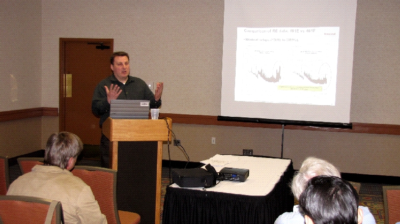
Keith Peavler, Chief Engineer EMC of Honeywell Aerospace, shows a rapt Phoenix crowd the incredible difference in E field levels as measured with MIL-STD-461E and 461F test setups below 30MHz. Photo by Steve Gerard.
Glen Gassaway reports that the first IEEE EMC Phoenix Chapter meeting of the fall was held on September 21st, 2010 at Garcia’s Mexican Restaurant in the Embassy Suites Hotel at Rural Road and I-60 in Tempe, AZ. The meeting began with the customary social hour starting at 5:30 pm, with dinner at 6:00. At 6:15, our chapter chairman Harry Gaul called the meeting to order while we were all enjoying Garcia’s excellent food. Harry announced that the beverages were being paid for by TMS marketing, Phoenix’s representative for ETS-Lindgren, Amplifier Research and Rhode and Schwarz (among others). Our chapter very much appreciated the free beverages! Harry then put out a call for speakers. Anyone that knows of an interesting and informative speaker that can present at the next chapter meeting should contact Harry or one of the other officers. We are looking forward to the possibility that our members from Honeywell will speak about rod antenna set up changes between MIL-STD-462E and F. Chapter business concluded with round table introductions and a call for EMC employment/employers Once dinner was over, we moved the meeting to the Junior Ballroom and Daryl Gerke introduced our featured speaker: Kevin Slattery, the Manager for Advanced Signaling and Interference Technologies at Intel. Mr. Slattery has been working in the field of EMI/EMC for 18 years and has developed measurement techniques and analytical approaches for the evaluation of high speed processors, chipsets, LAN, and display electronics. Mr. Slattery has been one of the pioneers in developing near field measurement techniques for the scanning of integrated circuits providing some of the first surface field distributions of high spatial resolution. He was also one of the pioneers in the use of broadband radiated emissions techniques with VLSI GHz TEM cells designed specifically for measuring integrated circuits. Both the near field scanning and GTEM measurements have become IEC standards. In addition, he works on RF interference mitigation, EMI/EMC and high speed clocking issues. He has over 35 publications in the fields of EMC and RFI. Previously, he was with DaimlerChrysler EMC in Huntsville, Alabama where he built an advanced EMI/EMC research capability. He has also worked in high energy physics at the Stanford Linear Accelerator Center where he was responsible for particle beam timing systems in storage rings and in beam transport systems in the linear accelerator. With the advent of mobile computing, wireless communication has become an integral part of the computer platform. Wireless is now ubiquitous in laptops, and modern cell phones contain several integrated communications devices. The problem is these devices were never intended to coexist. Communications devices have not been designed with high speed digital logic in mind. High Speed digital logic has never included communications as a design vector. The end result is that these devices don’t work well together and much shoehorning is currently undertaken to make them cohabit in the same device. That shoehorning generally incurs costs in terms of product delays and additional mitigation solutions. It is a sobering thought that 3 dB of noise can reduce the performance of your communications system by 50%. It is even more sobering that 20 or even 30 dB of noise is common on some devices. In various bands, emissions suppression requirements to provide compatibility between digital electronics and co-existing communications devices are 30 dB more stringent than meeting FCC radiated emissions requirements. Some solutions have involved the use of costly metal shielding. Other solutions are far superior. The designer needs to think that mitigation schemes are layered, where one can use a number of methods to achieve compatibility. The careful use of differential signaling can be beneficial, but it must be considered that imbalanced differential systems are not ideal because of differential to common mode conversion. Additionally, skew can radically detriment the emissions at the edges of differential signals. Skew of 75% of the waveform rise time can completely negate the benefit of differential signaling. Skew can be introduced by unequal trace or wire lengths, and can even be affected by changes in wire insulation relative permittivity. The speaker noted that in some cases it is reasonable to specify wire insulation permittivity along a wire’s length! Even with the best differential signaling design practices, one typically still needs 5-10 dB of additional isolation. Another digital technique involves the use of a pseudo-random bit stream. Synchronized periodic signals emit on the order of 20 dB more than random signals. When a system’s clock or synch signals are pseudo-random, significant interference reduction is achieved. The speaker told us of his experimentation with a variety of clock wave shapes, which he analytically and empirically optimized to achieve minimum noise at the system’s communications bands. Other techniques include careful selection of clock frequencies, which can be adjusted so high order harmonics do not reside within system receiver bands. If it is impossible to move a clock frequency that far, then it may at least be reasonable to change the clock frequency where an odd harmonics falls within the receiver band instead of an even harmonic (or vice versa). Attention to clock components is also critical. Some vendor’s clocks pay little regard to emissions, where trace layouts are not optimized for emissions control. Other vendor’s designs may have far lower emissions signatures. Some manufacturers only use auto routing for trace layout, while others pay close attention to the outer ring, but auto-route the core. The best manufacturer’s trace layouts provide symmetry everywhere on the chip. In addition, clock chips often radiate in a non-uniform manner, and knowledge of the emissions spectrum at different distances and directions around the chip is helpful. Antenna placement is also critical. It’s best to move communications antennas as far away from the emissions source as possible. As an example, a Wi-Fi antenna placed across the top of a laptop display can be very close to display drivers. There are also other mechanical control methods, such as the control of enclosure resonances. Where possible it is beneficial to design enclosure sizes to eliminate resonances at system communications bands. On-board power planes are also resonant, and clock chips and receiver circuitry can be strategically placed at non-resonant locations or nulls on boards. Finally, simply splitting the ground plane between the digital and communications sections on a single board can achieve up to 50 dB of additional isolation! After the presentation, Harry Gaul presented Kevin with a beautiful Arizona Highways Calendar for his excellent presentation. We would very much like to thank him for his time and effort! The meeting was called to a close at about 8:30 pm. Our thanks to all who attended! Click here to download a copy of Kevin Slattery’s presentation in PDF format.
Kevin Slattery provides some unique ideas to combat platform interference to a rapt Phoenix chapter of 30 attendees. Photo by Steve Gerard.
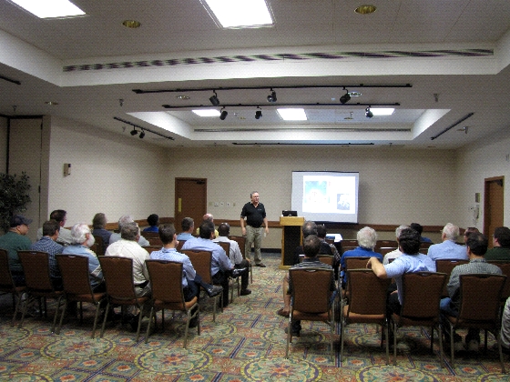
The April recent meeting of the IEEE EMC Phoenix Chapter was held on Wednesday, April 7th 2010 at Garcia’s Mexican Restaurant at the Embassy Suites Hotel at Rural Road and US-60 in Tempe, AZ. The meeting began with the customary social hour starting at 5:30 pm, with dinner at six. Again we had a large attendance, requiring us to move to a larger meeting room for the evening’s lecture. After we all had our fill of Garcia’s Mexican food, chapter chairman Harry Gaul called the meeting to order at 7pm. We then held our customary round table introductions and the call for EMC employment/employers. After the general chapter business was completed, we moved to the meeting room and Harry introduced our featured speaker: Dr. Sergiu Radu, Principal Engineer at Sun Microsystems. Dr. Radu is currently Principal Engineer at Sun Microsystems, leading the EMC Design group in Menlo Park, California. Dr. Radu received a M.S. and a Ph.D. in Electrical Engineering (Electronics) from Technical University of Iasi, Romania, and until 1996 he was an Associate Professor at the same university, involved in Electromagnetic Compatibility teaching and research. From 1996 until 1998 he was a Visiting Scholar at the University of Missouri-Rolla, as part of the Electromagnetic Compatibility Laboratory. In 1998 he joined the EMC Engineering group at Sun Microsystems. Dr. Radu holds seven US patents for EMI reduction techniques in electronic systems and has published more than 50 papers in research journals, symposia, and magazines. He is a reviewer for IEEE Transactions on EMC. He is also a distinguished lecturer for the IEEE EMC Society. Most electronic equipment uses some type of shielding, and from a theoretical point of view, electromagnetic shielding is among the difficult areas of EMC. Dr. Radu mentioned that the best way to resolve EMI issues is at the source, but shielding is often used when source suppression cannot be accomplished. Also, the shielding problem is different when one is trying to resolve emissions problems as opposed to susceptibility. In most RE situations, shields are in the near field with respect to the emitting sources. For immunity, the product is often in the far field with respect to the interfering source. The source antenna doesn’t matter in far field situations, since the wave impedance is by definition 377 Ohms. The antenna physical dimensions and placement are critical in near field situations, so board and wire placement are especially important for RE. In addition, reciprocity between RI and RE may not be valid since the problems are different: internal circuitry that may be a strong emitter typically radiates a low impedance field, while easily-susceptible internal circuitry is often high impedance. Dr. Radu then discussed the background of Schelkunoff’s and Kaden’s shielding theories. These theoretical approaches work well for shields which are infinitely large and without imperfections (such as apertures) and when the wave impedance is defined. In practice, shields usually are imperfect and sources are difficult to characterize. Often experimental methods are the only way to accurately validate analysis or numerical models. Some shielding structures have been experimentally evaluated using TEM cells per MIL-STD-285, IEEE-299 and other standards, but these methods also have limitations based on the size of the TEM chamber and their lowest order modes. These methods have proven useful for comparing unusual products which are difficult to analyze, such as conductive paints and composites. Another parameter to consider for box shielding is chassis resonance based on interior box dimension. An empty chassis can have first order modes which have extremely high Q, which may approach as much as 5000. Typical values of Q for a stuffed chassis are more like 10. Also, the mode order may make a difference because there is a different field distribution for different modes. Often, a small change in oscillator frequency may make a dramatic difference in emissions levels, since excitation pattern in the chassis may be much different for different modes. It is also important to point out that most of the energy is in the lowest mode orders. In some instances, the easiest way to resolve an emission at lower mode orders may be to make chassis geometry changes or slight frequency changes. Dr. Radu then discussed the leakage path through apertures. Eddy currents are detoured around an aperture, which, after a voltage drop due to material impedance, can generate a significant voltage across a narrow gap. This may result in a substantial radiated field. The Babinet’s principle says that a gap of known size replaced with a conductor of equal size provides a field of the same magnitude, only in the opposite polarization. That’s why the most critical dimension of a resonant slot is its longest dimension. Because of this principle, it is better to use many small holes for ventilation as opposed to one long hole. There are two rules of thumb that may be used to determine the largest aperture dimension or maximum fastener spacing for a cover: 1) Since internal chassis resonances have the most energy in lower order modes, multiply the lowest chassis mode by 5 and assure that any gaps have significant shielding at that frequency; 2) Make sure that any potential source antenna (e.g. wire) is located 5 times the longest aperture dimension from any given aperture. For instance, if an aperture is 9 mm wide, any internal emitting wire should be 4.5 cm away from the aperture. Honeycomb is the best vent material, but it can be expensive. Be sure to use plated honeycomb material to prevent leakage in one polarization. Honeycomb is also good in reducing air turbulence when using fans. When honeycomb cannot be used, try to use at least two layers of perforated shielding material – a second layer can add as much as 20 dB shielding. Shielding testing of a particular chassis may use S11 or S21 measurements made by network analyzers using small dipole radiators within the chassis and typical RE test antennas exterior to the chassis. Comb generators may also be used, as long as attention is given to non-uniformities of the comb generator spectrum. The meeting was called to a close at about 8:15 pm. This was our last meeting before the hot Arizona summer – so we will see you all next fall. Thanks to all who attended!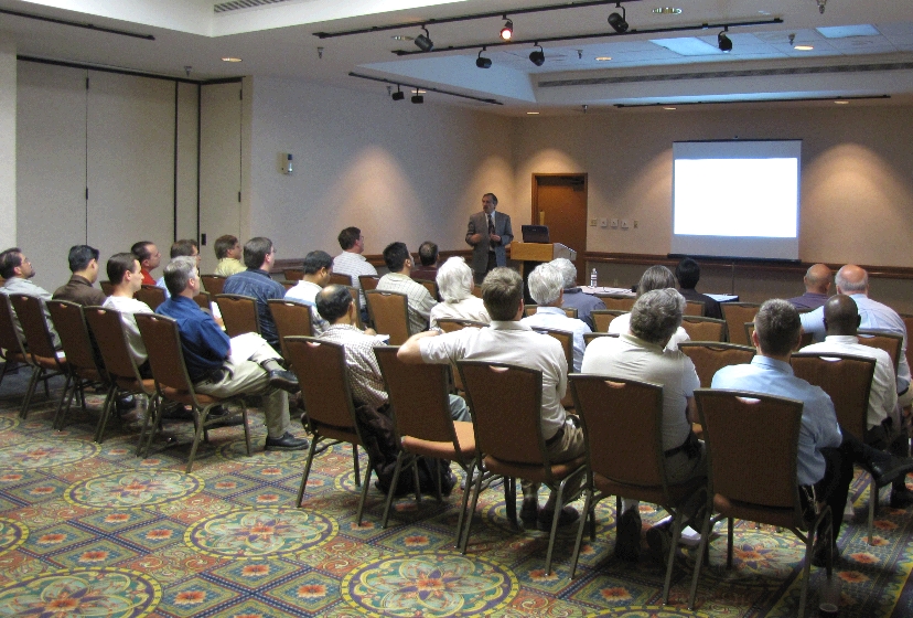
Dr. Sergiu Radu explains the benefits of using comb generators to measure shielding effectiveness to a large turnout in Phoenix. Photo by Steve Gerard.
On Thursday, February 25th, the EMC Chapter hosted Kyungjin “Jin” Mi, Chief Operating Officer, Amber Precision Inc. (API), who spoke on “EMC Immunity Scanning – A New Way to Look at System Level Immunity”. Jin filled in for Michael Hopkins who could not make it because of a broken leg. Jin brought Michael’s slow motion video clips of a lightning strike that proved to be of great entertainment to the 18 attendees. 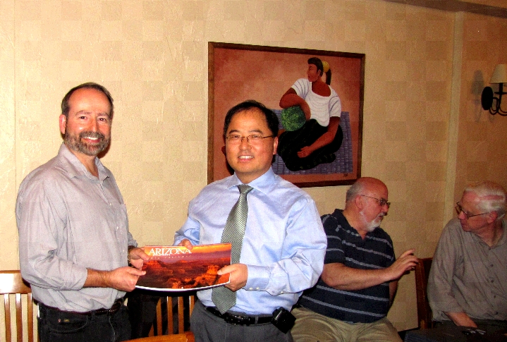
Harry Gaul presents Jin Min with an Arizona Highways calendar in appreciation for his presentation to the Phoenix Chapter on Immunity Scanning. Photo by Steve Gerard.
The first IEEE EMC Phoenix Chapter meeting of 2010 was held on Tuesday, January 19th 2009 at Garcia’s Mexican Restaurant in the Embassy Suites Hotel at Rural Road and US-60 in Tempe, AZ. The meeting began with the customary social hour starting at 5:30 pm, with dinner at six. This time we had the largest attendance ever, completely filling the meeting room and several tables outside of the meeting room! After we all had our fill of Garcia’s great Mexican food, chapter vice-chairman Daryl Gerke called the meeting to order. Daryl explained that the scheduled speaker, Kevin Slattery of Intel, was not able to make it due to transportation problems. So, our Chapter Chair, Harry Gaul, stepped in at the last minute to give a presentation. We then discussed future speakers, including Mike Hopkins, who will be presenting on EMC Immunity Scanning – A New Way to Look at System Level Immunity on February 25. We are also looking forward to a very interesting distinguished lecturer, Dr. Sergiu Radu, who will speak on PCB Design on April 7th. We then continued with our customary round table introductions and the call for EMC employment/employers. After the general chapter business was completed, Harry Gaul started his presentation. Harry is the Technical Manager of the EMI/EMC Group at General Dynamics C4 Systems in Scottsdale, AZ. He has been the Phoenix chapter chairman for over 10 years. He received his BSME from the University of Colorado in 1978 and an MBA from Arizona State University in 1998. Harry is a NARTE certified EMI/EMC Engineer and is a registered PE in the state of Arizona. As of October 1, 2011, the European Union will require product conformance to EN55022:2006 A1 (2007), which requires radiated emissions testing above 1 GHz for products with internal clocks greater than 108 MHz. No “grandfathering” will be allowed for products already on the market. In the past, Normalized Site Attenuation (NSA) testing was used to qualify a test facility for radiated emissions testing. However, NSA testing is not useful above 1GHz since directional antennas are typically used in that frequency range. To verify that a test facility is useful for testing above 1GHz, procedures for Site VSWR testing have been developed by CISPR/A and are presented in CISPR 16-1-4. The test methodology involves placing a receive antenna on a tripod and measuring the emissions of an omni-directional source antenna located in free-space or on a non-conductive (e.g., polystyrene) table. Eighteen source antenna positions are required in both horizontal and vertical receive antenna polarizations. Test frequencies should be in 50 MHz steps from 1 – 6 GHz. The source antenna positions extend along the center line of the turntable and along a ‘V’ formed by the edges of the test volume. Maximum versus minimum values cannot be apart by more than 6dB. Problems have been encountered when attempting to meet Site VSWR, especially in an absorber lined chamber. Potential areas of concern include: EUT table material (polystyrene blocks work well as opposed to wood or high density plastic), tripods, antenna positioners, door handles, floor absorber layout and wall absorber characteristics. The meeting was called to a close at about 7:45 pm. Our thanks to all who attended, as well as to TMS Marketing, who provided the drinks! 
Daryl Gerke thanks Harry Gaul for his presentation on Site VSWR measurements to the Phoenix Chapter. Photo by Steve Gerard.
The final IEEE EMC Phoenix Chapter meeting of 2009 was held on Monday, November 16th 2009 at Garcia’s Mexican Restaurant in the Embassy Suites Hotel at Rural Road and US-60 in Tempe, AZ. The meeting began with the customary social hour starting at 5:30 pm, with dinner at six. We had an excellent attendance, completely filling the meeting room. After we all had our fill of Garcia’s Mexican food, chapter chairman Harry Gaul called the meeting to order at 7:05 pm. Harry explained that next year’s agenda is already getting full, with three speakers lined-up for the first half of the year. As usual, we are always searching for interesting speakers for our chapter meetings. If you have any ideas for speakers, please contact one of the chapter officers. Harry also mentioned that we would be open to inviting vendors to present a 5-10 minute sales pitch for their products at our meetings, provided that they pay for the food and drinks! At that point we proceeded with the annual officer elections. The membership unanimously agreed to keep the officers the same: Harry Gaul as Chairman; Daryl Gerke as Vice Chairman; Glen Gassaway as Secretary and Jim Dykema as Treasurer. We then continued with our customary round table introductions and the call for EMC employment/employers. After the general chapter business was completed, Harry introduced the evening speaker: Bill Kimmel from Kimmel-Gerke consultants. Bill received his BSEE with distinction from the University of Minnesota, and has worked in the electronics field for over 40 years. His experience ranges from electronic design and systems engineering to technical management with industry leaders like Control Data Corporation and Sperry Defense Systems. His EMC experience includes the design/test/qualification of military systems to MIL-STD-461 and NACSEM 5100 (TEMPEST) and commercial systems to FCC Part 15 and IEC/CISPR. He has solved EMI problems in computer systems, medical devices, industrial controls, vehicles, telecommunications systems, and more. He has several years experience in radiation hardened circuits and high speed memories for computers. He is a Registered Professional Engineer, an active member of the IEEE, and a NARTE certified EMC and ESD Engineer. Bill began his presentation entitled: “ESD as an EMI problem”. He talked about situations where ESD becomes a problem, mentioning that the EU and Pacific Rim are largely maritime climates and have fewer issues with ESD than North America, where industrialized areas are often located in very dry climates. He mentioned that the primary cause of ESD failure is excess voltage between signal and ground pins on chips, causing ground bounce. It is important to divert ESD currents away from chips through shielding and filtering. It is also important to realize that ESD can follow two paths: direct or indirect discharge. Bill then presented the Ten Keys to ESD control, including avoiding static buildup, preventing the discharge from occurring, the use of multi-layer boards, filtering critical lines, filtering critical circuits, internal wire routing, use of metal connector backshells, omitting pigtails as shield terminations, using the right shielding material and error correction in software. Bill’s presentation was chock-full of excellent design hints! Our thanks for Bill for a very enlightening presentation. After the presentation, Harry presented Bill with a 2010 Arizona Highways calendar. 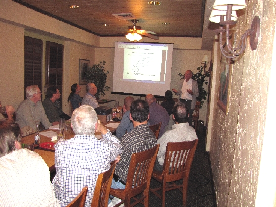
Bill Kimmel of Kimmel-Gerke Associates points out to the Phoenix Chapter that ESD is a major problem for keypads. Photo by Steve Gerard.
Harry Gaul reports that the second meeting in 2009 of the IEEE EMC Phoenix Chapter featured Dr. Bruce Archambeault who spoke on The Ground Myth. Bruce is an IBM Distinguished Engineer at IBM in Research Triangle Park, NC. This meeting was held in conjunction with one of the EMC Society’s quarterly Board of Directors meetings. A total of 65 people attended this presentation. Bruce started his talk with a little history about Scotland. He noted that Maxwell was the greatest contribution from Scotland after Scotch. Bruce emphasized the point about the return current will always find the path of least impedance back to its source. As EMC Engineers, it’s either up to us to control that path or it will be up to God and Maxwell to figure it out. The bottom line is “How lucky do we feel today about the current getting back to its source?” Bruce provided some interesting insight to so-called differential signal traces. First, these traces actually have significant current flow into and out of the signal reference planes because of the close proximity between the pair traces and the planes. Thus, careful consideration must be used when routing these traces above reference planes to ensure the traces do not encounter discontinuities in the planes such as gaps. Also, unequal trace lengths of the differential traces will create timing skew that may minimally affect signal quality but will create large common mode currents, which are responsible for most EMC problems. Bruce’s presentation slides are available for downloading by clicking on this link.
The March meeting of the Phoenix Chapter was held in conjunction with the EMC Society’s Board of Directors meeting. Sixty-five people attended on a Friday night to socialize and to hear an excellent talk from Dr. Bruce Archambeault on grounding. Photo by Steve Gerard.
Harry Gaul reports that the first meeting in 2009 of the IEEE EMC Phoenix Chapter featured Dr. Eric Bogatin who spoke on The Ten Habits of Highly Successful Designers. Eric is a Distinguished Lecturer for the EMC Society and he is a signal integrity evangelist for Bogatin Enterprises, which specializes in signal integrity training and education. A total of twenty-nine people attended this presentation. Eric stressed the importance of watching out for six problem areas for signal integrity including reflections, crosstalk, ground bounce, dielectric losses, voltage droop and EMI. The root causes should be identified and design guidelines (habits) should be established to minimize the problems. Some of the habits include designing all interconnects as controlled impedance, using multiple ground and power planes on adjacent layers, using as many decoupling caps as you can place on the board, and not crossing gaps in return planes with signal traces. A wealth of information including this talk is available on Eric’s web site at http://www.bethesignal.com. 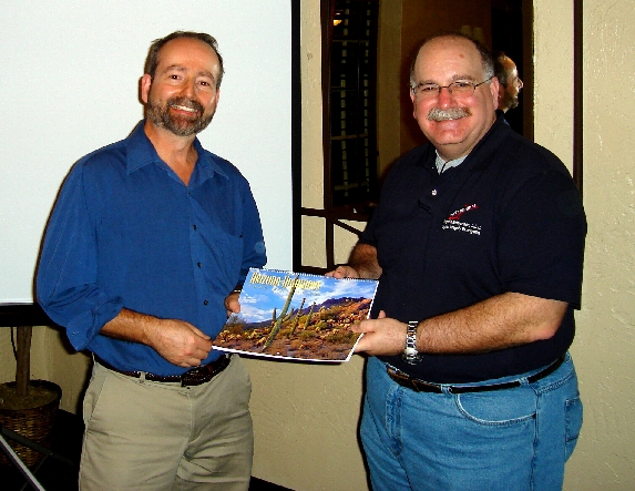
Harry Gaul presents Eric Bogatin of Bogatin Enterprises with an Arizona Highways calendar as thanks for his excellent talk on signal integrity to the Phoenix Chapter. Photo by Steve Gerard.
Harry Gaul reports that the fall meeting of the IEEE EMC Phoenix Chapter meeting was held on November 3rd, 2008 at Garcia’s Mexican Restaurant in Tempe, AZ. The featured speaker was Daryl Gerke, who is a partner with Kimmel Gerke Associates, Ltd., an engineering consulting and training firm that specializes in EMI/EMC issues. Daryl’s talk provided insights on EMC in power electronics. He discussed some special problems, such as parasitic coupling and high frequency emissions in power supplies. He also provided tips and techniques on transient protection, power filters, and RF hardening. Daryl pointed out that one of the biggest problems in power supplies is the parasitic coupling associated with heat sinks mounted to power MOSFET’s. Various techniques can be used to reduce these emissions including isolating the heat sink from the chassis or using a shielded heat sink. An additional tip is to try inserting ferrite beads in the primary and secondary leads of the switching transformer to reduce high frequency emissions around 50MHz

Harry Gaul of the Phoenix Chapter presents Daryl Gerke of Kimmel-Gerke Associates with an Arizona Highways calendar in appreciation of his talk on EMC in Power Electronics. Photo by Steve Gerard.
The second IEEE EMC Phoenix Chapter meeting in 2008 was held on Wednesday, May 21st, 2008 at the National Technical Systems (NTS) environment test lab in Tempe, AZ. The meeting was in conjunction with an open house that NTS was having that same day. The meeting began with a lab tour. NTS showed off their complete environmental test facility (including EMI) to our Phoenix Chapter participants. After the initial tour, the meeting continued with the customary social hour combined with a great barbeque dinner furnished by NTS. The meeting was very well attended including many old and new faces! After the general chapter business was completed, Harry introduced the evening speaker: Mr. James Press. Mr. Press has been working in the EMC field for over 22 years. In his present position as Director of National EMC Operations for National Technical Systems, he is involved in commercial, military, nuclear and telecommunications EMC design and test. National Technical Systems consist of environmental laboratories worldwide with 7 containing EMC capabilities. Mr. Press is responsible for all EMC technical issues and development nationwide. Mr. Press has been on the MIL-STD-461D/E, TR-102323, SAE AE-2, DO0160F/G, Defense Industry Steering Committee (DIESC) and AREMA EMC Committees. Mr. Press holds a BA from Temple University and a MS from Iowa State University, both in Physics. He has published over 20 articles and a handbook on EMC test and design. Mr. Press is NARTE certified EMC Engineer. Mr. Press’s presentation provided an overview of MIL-STD-461E and 461F and the major difference of the two standards. All tests methods were covered and the audience was able to ask questions and provide comments to the MIL-STD’s. Our thanks for Jim for a very enlightening presentation! The chapter continued to informally socialize and tour that facility after the presentation. The meeting was called to a close at about 8:30 pm. Stay tuned for upcoming speakers. Our thanks to all who attended!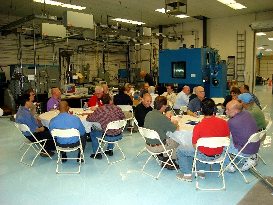
The Phoenix Chapter enjoys a hearty barbeque dinner in the environmental lab at National Technical Systems (NTS) in Tempe, Arizona. Photo by Steve Gerard.
Mr. James Press of NTS discusses the differences between MIL-STD-461E and the newly released MIL-STD-461F to the Phoenix Chapter. Photo by Steve Gerard.
Harry Gaul reports that the January 2008 meeting was hosted by General Dynamics AIS at their Arizona Space Center Manufacturing Facility in Gilbert. Thirty-five people enjoyed the barbeque dinner and then listened to presentations on EMC design and testing of satellites by General Dynamics EMC Engineers, Glen Gassaway and Brian Daniel. Glen explained the history on the development of their state-of-the-art EMC test chamber where they test everything from box level to subsystem level to actual spacecrafts at the system level. Efficiency in testing is especially important because of the critical timelines in space programs. Glen mentioned that any delay in the testing of a spacecraft will translate to a cost of $100,000 per day. One technique to quickly assess the EMC of a spacecraft is to connect the output of on-board antennas directly to a spectrum analyzer in order to determine if there are any in-band unintentional emissions present. Brian Daniel outlined the engineering aspects of satellite development including the definition of test limits with special tailoring for receiver notches. Generally, vehicle compatibility while in orbit is the biggest concern although one must also consider the high RF levels that are present at the launch site. Brian said that 10% to 15% of a space vehicle’s weight can be attributed to the copper wiring. Cables are typically shielded by wrapping mesh tape around them. Following the presentations, the attendees were escorted on a tour of the facility including the EMC test chamber that measures 27 feet by 30 feet by 21 feet high. This chamber is equipped with a 14 foot wide by 20 foot high mechanized sliding door plug that enables test articles to be rolled into the chamber over a smooth level entry. This facility not only supports in-house work but it is also available for outside business. Information on future meetings is available on the Phoenix EMC Chapter Web site at http://www.site.ieee.org/pheonix-emcs/

The Phoenix Chapter enjoyed a tour of the EMI/EMC Laboratory at General Dynamics AIS in Gilbert, AZ. This facility was built in 2004 and has already been used to test six space satellites
The fall meeting of the IEEE EMC Phoenix Chapter meeting was held on November 7, 2007 at Garcia’s Mexican Restaurant, in the Embassy Suites Hotel at Rural Road and I-60 in Tempe, AZ. The meeting began with the customary social hour starting at 5:30 pm, with dinner at six. After we all had our fill of Garcia’s excellent food, Harry Gaul, our chapter chairman, called the meeting to order at 7:00 pm. The first order of business was the election of chapter officers for the new season. After some discussion and an informal vote, the chapter decided to retain the existing officers for another year. Harry then put out a call for speakers. Anyone that knows of an interesting and informative speaker that can present at the next chapter meeting should contact Harry or one of the other officers. Chapter business concluded with round table introductions and a call for EMC employment/employers.
Harry then introduced our featured speaker, Joe Butler of Chomerics. Joe currently has the dual roles of New Business Development Manager and Conductive Elastomers and Compounds Product Development Manager at Chomerics. He has over 35 years experience as an electromagnetic compatibility engineer. He is a senior life member and Past-President of the IEEE EMC Society and is also a past member of the IEEE EMCS Standards Committee. He is a NARTE certified EMC engineer and is a past member of the Board of Directors of NARTE. Joe has a BS in Engineering Physics from Merrimack College, an MA in Physics from Williams College, and an MBA from Northeastern University.
Joe started his presentation on shielding effectiveness testing of EMI shielding materials (such as EMI gaskets, paints, shielded windows and vents) by mentioning that the industry does not have a consensus standard in place. Rather, the test methods for shielding effectiveness range from variants of the long ago retired MIL-STD-285 to the more recent IEEE-STD-299. For military oriented products, the shielding data is quite often a result of a modified MIL-DTL-83528 test method. Although Joe described several shielding test methods for various products from various sources, the majority of shielding effectiveness data tends to be derived from radiated field testing methods. While many large corporations that have EMC groups on staff may use transfer impedance and reverberation chamber test methods due to their more inherent accuracy and repeatability, most vendors of shielding components have not followed their lead. The reasons for this difference in approach run from factors such as lack of resources, the comfort level of the vendor EMC engineers in interpreting the internally generated data, to the inherent frequency limitations of these latter test techniques when contrasted against the market need for 30 MHz to 40 GHz shielding effectiveness test data needed to market the products.
Current standards activities include revisions to IEEE-STD-299, generally creating three methods based on enclosure size. These activities are trending more towards reverberation chamber techniques, generally thought of as the most accurate. Unfortunately, these techniques may generate test data that makes shielding products look ‘worse’ than presently-used methods. For this reason, as well as cost and resources, most shielding manufacturers have not yet incorporated reverberation techniques as part of their material test programs.
Joe mentioned that some customers have recently been interested in assurances of long-term reliability through post environmental testing (such as ALT). The industry is also interested in 94V-0 flammability ratings, RoHS and other “green” initiatives. Customers have requested elemental analyses of various products. Material shielding effectiveness using modern trivalent coatings (MIL-C-5541F) has also been an issue. Some agree that new standards are needed for these trivalent coating techniques.
After the presentation, Harry Gaul presented Joe with a beautiful Arizona Highways Calendar for his excellent presentation. We would very much like to thank Joe Butler for his time and effort! The meeting was called to a close at about 8:00 pm. Our thanks to all who attended!
Joe Butler of Chomerics points out current standards committee work on shielding effectiveness standards to the Phoenix Chapter. Photo by Steve Gerard.
Download Joe Butler’s presentation by clicking here.
Harry Gaul reports that 18 people attended the May meeting of the Phoenix EMC Chapter. Dave Staggs gave a brief presentation on the upcoming EMC Symposium and 50th anniversary celebration of the EMC Society to be held in Hawaii this summer. Dan Hoolihan was the featured speaker with a topic entitled “Understanding the Latest Changes to IEC 17025 for EMC Lab Accreditation.” Dan began his talk by offering suggestions on how to select an EMC Lab. First, you should make sure the lab is accredited to ISO17025:2005 and then verify that the scope of accreditation covers all of your tests. The ISO17025 document covers all kinds of labs, not just EMC. The document includes both management requirements as well as technical requirements. One of the highlights of ISO17025 is that a lab needs to seek feedback from its customers, both positive and negative. Also corrective action using root cause analysis should be undertaken to correct error prone processes. In particular, Dan mentioned that a lab’s measurements should always fall within plus or minus two standard deviations. This should be checked on a routine basis by performing intermediate checks such as measuring the E-field level of an FM radio station.

Dan Hoolihan presents Tom Karas of Motorola and Jim Vogler of National Technical Systems with IEEE beach towels to commemorate the 2007 EMC Symposium in Hawaii. Tom and Jim won the towels as door prizes at the May meeting of the Phoenix Chapter. Photo by Steve Gerard.
The third IEEE EMC Phoenix Chapter meeting of the 2006-2007 season was held on February 21, 2007 at Garcia’s Mexican Restaurant, in the Embassy Suites Hotel at Rural Road and I-60 in Tempe, AZ.
The meeting began with the customary social hour starting at 5:30 pm, with dinner at six. Again, we had a excellent attendance, with even more new faces than December’s meeting!
After we all had our fill of Garcia’s Mexican food chapter chairman Harry Gaul called the meeting to order at 7:15 pm. Business began with the introduction of our new chapter officer, as Jim Dykema has joined us as treasurer. Welcome Jim! We then continued with our customary round table introductions and the call for EMC employment/employers. We are also searching for any interesting speakers for our next chapter meeting. If you have any ideas for speakers, please contact one of the chapter officers.
After the general chapter business was completed, Harry introduced our featured speaker, Michael J. Oliver of MAJR Products Corporation.
Mr. Oliver is Vice President of Electrical / EMC Engineering at MAJR Products Corporation responsible for customer technical quoting and consulting, new product development, and is the ISO-9001:2000 management representative. His expertise is in EMI/RFI shielding technology with a background in electronics, military shelter electrical systems, and high power antenna / radome design. He holds a B.S. degree in Electrical Engineering from Gannon University and has been an Electrical Engineer since 1989. He currently holds three patents (two pending), on EMC shielding – thermal management devices. He currently serves as Chairman of the newly formed IEEE Pittsburgh EMC Society, Vice Chairman of the SAE AE4 Electromagnetic Compatibility Committee, and member of the IEEE EMC Standards Advisory Coordination Committee (SACCom).
Mr. Oliver started the presentation by reviewing EMC fundamentals, including basic definitions of EMC terminology. He mentioned a very interesting Georgia State University web site at http://hyperphysics.phy-astr.gsu.edu/hbase/hframe.html, which has an excellent glossary of electromagnetic and other Physical terms. He pointed out the distinctions between Differential Mode versus Common Mode noise interference generation, and potential mitigation methods for each (including shielding). He mentioned that common mode interference is generally more predominant. He also discussed Plane Wave versus E-Field and H-Field shielding, and provided equations for each. A good rule of thumb dictates that material type dominates shielding effectiveness below 10 MHz and holes or apertures dominate shielding above 10 MHz. He also mentioned how partial shields may not operate as intended since they can actually increase emissions on the ‘unshielded’ side.
Mr. Oliver then discussed the MIL-DTL-83528 shielding test method, and recommends that non-conductive bolts or fasteners should be used when making this measurement. He also mentioned that Beryllium-Copper makes an excellent shielding material, but care should be used in instances where RoHS compliance is mandatory. According to Mr. Oliver, 2% beryllium is generally considered acceptable.
Mr. Oliver then explained concepts of aperture shielding. For slot apertures, shielding can be estimated by the equation SE = 20 log (Lambda/2L), where L is the longest dimension of the slot. Hole aperture shielding can generally be estimated by SE = 40 log (Lambda/2L). If multiple apertures are present, shielding loss is proportional to 20 log N, where N is the number of apertures within Lambda/2. MAJR Products Corporation has an excellent Excel-based design tool to assist with shielding calculations at their website: http://www.majr.com/.
Regarding Honeycomb vent panels, a 4:1 thickness to width ratio is considered ideal. Remember that nickel or tin plating is important to reduce the effect of ‘Glue Lines’ in the honeycomb material. Mr. Oliver recommended MIL-STD-1250 as a good resource for galvanic corrosion.
After the presentation, Harry Gaul presented Mr. Oliver with a beautiful Arizona Highways Calendar for his excellent presentation. We would very much like to thank Mr. Oliver for his time and effort!
The meeting was called to a close at about 8:30 pm. Stay tuned for upcoming speakers. Our thanks to all who attended!
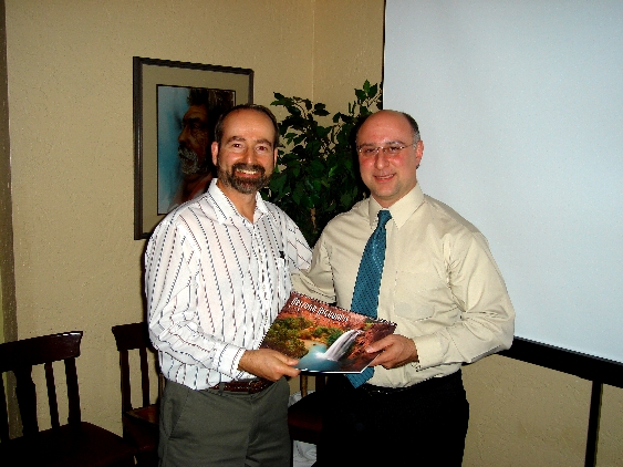
Harry Gaul presents Mike Oliver with an Arizona Highways calendar on behalf of the Phoenix Chapter. Photo by Steve Gerard.
Click HERE to download Michael Oliver’s presentation on Shielding Theory and Design.
The second IEEE EMC Phoenix Chapter meeting of the 2006-2007 season was held on December 6th 2006 at Garcia’s Mexican Restaurant, in the Embassy Suites Hotel at Rural Road and I-60 in Tempe, AZ. The meeting began with the customary social hour starting at 5:30 pm, with dinner at six. We had a good attendance, with many new faces! We were also pleasantly surprised by the attendance of a long-time IEEE-EMC and SAE member that we have not seen in a while – Dwayne Awerkamp. After we all had our fill of Garcia’s Mexican food, Harry Gaul, our chapter chairman, called the meeting to order at 7:00 pm. Business began with the customary round table introductions and the call for EMC employment/employers. We welcomed Hoosamuddin Bandukwala from Flom Test Labs, who mentioned that they may be looking for EMI Engineers and Technicians in the near future. Harry Gaul also mentioned that it has been quite a while since we have had officer elections in our chapter, so he opened the floor to nominations for Chapter Chairman, Vice Chair, Secretary and Treasurer. Because of the overwhelming number of volunteers and nominees, Harry, Glen and Daryl continue to be the chapter officers! After the general chapter business was completed, Harry introduced our featured speaker, Mr. Gary Fenical of Laird Technologies. Mr Fenical is an EMC Technical Sales Representative at Laird Technologies in Delaware Water Gap, PA and has been with the firm for 23 years. Mr. Fenical has authored many articles on EMC Requirements for Medical Devices, Mutual Recognition Agreements and Guidelines to meet the essential requirements of the EMC Directive. He has also authored several seminars on the EU EMC Directive, International Compliance and Designing for EMC and EMC Requirements for Medical Devices, which have been presented worldwide. At the end of 2004, the European Council and the European Parliament have formally adopted a revised Directive on Electromagnetic Compatibility (EMC Directive): the new Directive 2004/108/EC of the European Parliament and of the Council, of 15 December 2004, on the approximation of the Laws of Member States relating to electromagnetic compatibility, published in the OJEU on 31 December 2004 (L 390/24). This new Directive will replace the old Directive 89/336/EEC within three years (from 20 July 2007). The mandatory application of the new directive is 20 July 2009. Mr. Fenical’s presentation was a summary of a series of presentations that he attended in Brussels in February 2005. He was one of only a handful of US attendees, and therefore provides us with valuable insight into the impact of the new directive. The new approach directive stresses meeting the essential requirements through the use of harmonized standards. The use of Technical Construction Files is removed. A manufacturer may choose to use harmonized standards (generally preferred) or may choose to use a technical file approach. The new directive was a result of the 1998 SLIM report, which was the output of a panel of experts who advised the member states to clarify the original directive’s scope and definitions, and to better define the essential requirements. Mr. Fenical went on to describe the directive’s definitions of Apparatus, Component, Passive Equipment and Mobile and Fixed Installations. One of the most important regulatory changes is how Fixed Installations are handled. No longer do all of the individual apparatus contained in fixed installations need to comply with the directive, as long as the fixed installation itself meets the essential requirements. Often this can be accomplished through the use of a technical file, which must be kept with the person responsible for the fixed installation and at the disposal of the national authorities. As the apparatus are imported, they must be clearly marked that they are part of the fixed installation in order to clear customs. Exceptions to the new directive include RTTE (telecon equipment), Aeronautical equipment, and Amateur radio equipment. It is also important to note that the Harmonized Standards have not changed as a result of the new directive and they must be applied within their scope. Full responsibility of compliance is placed on the manufacturer or importer (in fact, it always has been), but the new directive does not require mandatory competent/notified body involvement if harmonized standards are not used. Mr. Fenical also spoke of configurations and operating conditions of test items, including the use of ‘normal operating conditions’ unless a single worst-case operating condition can be identified. Product marking, traceability to the responsible person, precautions of use and clear restrictions of residential versus industrial operating environment are required. Technical files must be kept with the manufacturer for at least 10 years and Declarations of Conformity must have the required information and must be available to the authorities. Market surveillance in the EU is a multi-tiered approach, including reacting to interference complaints, authorities attendance at trade fairs, surveillance of notified bodies, and inspection of fixed installations. Several members of the EU are serious about EMC, and are not to be taken lightly. Generally, the new directive provides legislative changes only, and will not immediately affect most manufacturers or importers into the EU member states. However, it is very important to understand the upcoming changes of the European EMC directive so we can all be prepared. Our thanks to Gary Fenical for a very informative lecture! After the presentation, Harry Gaul presented Gary with a beautiful Arizona Highways Calendar for his efforts. The meeting was called to a close at about 8:30 pm. Our thanks to all who attended!
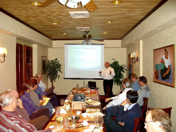
Gary Fenical of Laird Technologies explains the details of Europe’s new EMC Directive to the Phoenix Chapter... Photo by Steve Gerard.
The October IEEE EMC Phoenix Chapter meeting was held on October 29th at Garcia’s Mexican Restaurant, in the Embassy Suites Hotel at Rural Road and I-60 in Tempe, AZ. The meeting began with the customary social hour starting at 5:30 pm, with dinner at six. After we had our fill of Garcia’s great Mexican food, Harry Gaul, our chapter chairman, called the meeting to order at 7:00 pm. We had a good turn out with over a dozen EMC’ers attending. Our featured speaker was Dr. Flavio G. Canavero, who received the Laurea degree in electronic engineering from the Politecnico di Torino, Torino, Italy, in 1977, and the PhD degree from the Georgia Institute of Technology, Atlanta, USA, in 1986. Currently he is a Professor of Circuit Theory and Electromagnetic Compatibility with the Department of Electronics, Politecnico di Torino. He is also presently the Editor-in-Chief of IEEE Transactions on Electromagnetic Compatibility, and will soon move on to become the editor of technical papers for the IEEE EMC newsletter! Dr. Canavero started his presentation by explaining that Embedded/Integrated systems are becoming much more prevalent, and interact directly with the environment around them. Examples include ABS braking systems, entertainment systems, GPS receivers (in automobiles) just to name a few. These kind of embedded systems often have several integrated functions,, making EMC more important than ever. With time-to-market being a competitive driver, performing accurate simulations in the design phase without a prototype yet being available can be a competitive advantage. Dr. Canavero discussed a three part simulation tool set that can be used to model three parts of a circuit, the integrated circuit, the interface bus/interconnects and connectors/discontinuities. The first part of the tool set is known as Mpilog, which stand for “Macromodeling via Parametric Identification of Logic Gates. Mpilog generates behavioral macromodels for the I/O ports of digital integrated circuits. Mpilog macromodels are mathematical relations approximating the port electrical behavior of devices, thus completely hiding the internal structure of devices and preserving the proprietary information of vendors. Mpilog allows the implementation of macromodels as SPICE-like subcircuits or as direct equation descriptions via metalanguages like VHDL-AMS. Furthermore, macromodels can be directly used in any EDA tool supporting the IBIS ver. 4.1 description of digital integrated circuits as externally defined models. The second part of the tool set is know as IdEM, which stands for Identification of Electrical Macromodels. It is aimed at the generation of macromodels for linear lumped multiport structures (e.g., connectors, packages, vias, discontinuities, …), known from their input-output port responses. The input-output characterization of the structure under investigation can come from measurement or simulation, either in frequency domain or in time domain. A SPICE link allows the automatic synthesis of the macromodels into equivalent circuits that can be processed by standard circuit solvers. The third tool is knows as TOPLine, which is used to develop macromodels for busses and interconnects. Each of these tools generate output models that can be used as building blocks for simulations of large circuits or systems. Throughout the presentation, Dr. Canavero showed validations of the tools results. The final summary indicated that large circuits, which either took inordinate amounts of time to simulate, or could not be simulated at all using typically available computer hardware, were solved within reasonable time frames using the simulation tool set that Dr Canavero demonstrated. For further information, please see Dr. Canavero’s website at:http://www.emc.polito.it/home.asp. After the presentation, Harry Gaul presented Dr. Canavero with a beautiful Arizona Highways Calendar for his efforts. Our chapter thanks Dr. Canavero for a very interesting lecture and our thanks to all who attended!

In his talk on Electromagnetic Compatibility of Integrated Systems, Dr. Flavio Canavero explains to the Phoenix Chapter the need to account for additional properties beyond the IBIS models. Photo by Harry Gaul.
Glen Gassaway reports that the featured speaker in March was Dr. Franz Schlagenhaufer of the Western Australian Telecommunications Research Institute (WATRI). The meeting began with the customary social hour starting at 6 pm. After we had our fill of Garcia’s great Mexican food, Harry Gaul, our chapter chairman, called the meeting to order at 7:00 pm. It was immediately apparent that we had another excellent turn out, with over 20 persons attending, including one from Tucson. Dr. Schlagenhaufer told us that numerical field simulation is a useful tool for achieving electromagnetic compatibility on a system level. Numerical field simulation results may not have extreme accuracy on complex system models (as may be necessary for precise RF models), but generally EMC problems do not require that level of accuracy. During the simulation process, it is important to neglect as many unimportant details as possible to speed up the simulation, while keeping essential details. Therefore, performing meaningful simulations can be somewhat of an art form. System simulations are not meant to replace actual measurements, but are very useful in providing problem insight, supporting problem solving, and predicting the responses of design modifications. Situations when numerical simulations should be performed include: a) when the product is not available (such as shipboard antenna structures), b) when controlled variations of parameters are not possible (such as lightning strikes on transmission lines) and c) when the physical value of interest is not easily obtainable (such as the inductance value of complex structures). Dr. Schlagenhaufer’s presentation addressed the five basic steps of a typical simulation procedure: Modeling, Meshing, Computation, Result Validation, and Post-Processing Routines. Modeling includes transforming the physical model into a mathematical one. It is important to simplify and neglect non-essential parts of the physical model. It is important to know if the modeling assumptions are reasonable, and if adequate computer resources are available. Meshing includes converting the model into something the computer can understand. Segment sizes should be based on wavelength and structural discontinuities. Computation is generally done by the program itself. Presently available software is usually very accurate, but the output is only as good as the model. Before attempting the computation process, it is important to estimate calculation time and computer resource requirements. Result validation is often done by reviewing boundary conditions, power budget, field and current distributions and the model’s sensitivity of the variation of input data. Post-processing is required to display the results in a meaningful manner. Perhaps the best data display could be a set of observation points versus frequency, an observation line, or an observation plane. Combinations of these or other displays may also be meaningful. Dr. Schlagenhaufer closed the presentation with the following remarks: When it comes to field simulation for complex systems, some particularities can be noted. The outcome from the simulations will, in most cases, not be the final result, but rather the simulation results will be the input data for further systems analysis. After the presentation, Harry Gaul presented Dr. Schlagenhaufer with a beautiful Arizona Highways Calendar for his efforts. Our chapter thanks Dr. Schlagenhaufer for a very interesting lecture! 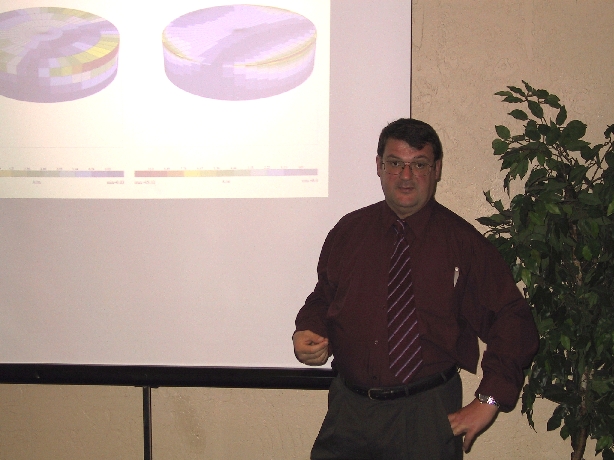
In his talk on electromagnetic modeling, Dr. Franz Schlagenhaufer explains to the Phoenix Chapter the need to increase the mesh density near edges where the current is rapidly changing. Photo by Steve Gerard.
The IEEE EMC Phoenix Chapter was proud to host the January 2006 RF-EMC-Wireless Tech Tour at the Embassy Suites Hotel in Tempe, Arizona. The RF-EMC-Wireless Tech Tour is an on-going series of technical learning sessions that will travel to Melbourne, FL, the Metro D.C. area and to Boston, MA later this year. Registration began promptly at 12:30 and it was soon apparent that this was to be a well-attended event. Once everyone was seated, the first presentation started on time at 1pm. The first paper was presented by the IEEE Phoenix Chapter’s own chairman Harry Gaul, who presented a paper on “The Influence of Ground Plane Reflection on Antenna Calibration and Measurements”. This presentation started out with a riddle: Which configuration is likely to have a better chance of reception given a 2 km distance between antennas at 450 MHz with a height of 2 meters (assuming a direct line of sight): across a still lake; across a golf course with mounds; or would both scenarios be equal? Harry’s presentation provided the theory and details of performing antenna calibrations in both free space and ground plane configurations in accordance with standards such as ANSI C63.5 and SAE ARP958. The concept of Normalized Site Attenuation (NSA) was introduced as a means to derive the difference between free space and ground plane test configurations. Antenna range measurements were also discussed from the standpoint of how to include the effects of reflection from earth with finite conductivity. It was concluded that ground plane reflections can induce serious errors if not properly accounted for during antenna calibrations and measurements. The effects of specular ground plane reflections can easily be modeled with today’s sophisticated mathematical software and additional considerations should include mutual coupling and the effects of cables. By the way, the answer to the riddle is that the golf course is more likely to provide good reception because of the deep nulls that are possible from the lake. The second paper, entitled “Anechoic Chamber Solutions for Antenna Pattern Measurements (APM)”, was presented by Dr. Vince Rodriguez of ETS-Lindgren. This presentation introduced the user to antenna ranges, and concentrated on rectangular and tapered anechoic chambers for APM. Rectangular chambers tend to have less critical source placement, and are the ideal configuration for swept frequency measurements. Tapered chambers tend to be better for lower frequencies, but have potentially higher bore sight errors. Absorber technology, quiet zone levels, and far field requirements were discussed as well as the proper absorber treatment for both tapered and rectangular chambers. Large compact range chambers were also discussed. The final paper, entitled “Improving the Accuracy of EMI Emissions Testing”, was presented by James Young of Rohde & Schwarz. This presentation discussed the advantages and disadvantages using a spectrum analyzer versus an EMI Receiver to make EMI measurements. Spectrum analyzers must be used carefully due to the possibility of reduced frequency accuracy over large frequency ranges. For example, a span of 970 MHz (30 MHz to 1 GHz) results in approximately 1 MHz frequency resolution if the spectrum analyzer has 1001 bins across its display. Given a 120 kHz CISPR bandwidth over this range, the bin size is larger than the bandwidth, and frequency resolution is lost. Additional concerns regarding EMI measurements with spectrum analyzers include less control of dwell time, potential 3 dB versus 6 dB resolution bandwidths, and less dynamic range and overload protection. However, the spectrum analyzer is a very versatile instrument, and may be used for EMI measurements as long as its limitations are well understood. The presentation suggested that a spectrum analyzer or test receiver may be used for initial scanning to make a frequency “hit-list” as well as for maximization, and that the test receiver is optimal for making final measurements. The presentation went on to review the issues of RF and IF overdrive as well as the problems and benefits of using low noise amplifiers for increased sensitivity. Once the presentations were complete a reception was held with the speakers, including hands on demonstrations and a drawing for prizes. Congratulations to Dennis Kennedy for winning the IPOD and David Lee for winning the 1GB memory stick. The IEEE Phoenix Chapter wishes to thank all of those who made the Tech Tour possible, including the sponsors: Rohde and Schwarz, ETS-Lindgren, TMS Marketing, and Conformity Magazine. We would like to thank all of those who participated in this very successful event!

James Young of Rohde & Schwarz speaks to over 60 people that attended the ½ day Tech Tour Workshop, which was hosted by the Phoenix Section. Photo by Steve Gerard.
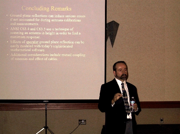
Phoenix Chapter Chair, Harry Gaul, concludes his presentation with a discussion of other sources of errors that can occur when performing antenna measurements and calibrations. Photo by Steve Gerard.
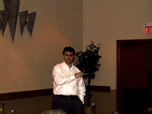
Dr. Vince Rodriguez of ETS-Lindgren points out the differences in rectangular and tapered anechoic chambers for antenna pattern measurements to the Phoenix Chapter.Photo by Steve Gerard.
Glen Gassaway reports that the November 2005 IEEE EMC Phoenix Chapter meeting was held on November 9th at Garcia’s Mexican Restaurant, in the Embassy Suites Hotel at Rural Road and I-60 in Tempe. This was the second meeting of the 2005/2006 season. The meeting began with the customary social hour starting at 6 pm. After we once again had our fill of Garcia’s wonderful food, Harry Gaul, our chapter chairman, called the meeting to order at 6:55 pm. Business began with roundtable introductions and the call for EMC employment/employers. Harry then discussed potential upcoming chapter meetings and announced the upcoming “Tech Tour: Aerospace EMC” Half-Day Technical Seminar, which will be held on Wednesday, January 25, 2006 in the same Embassy Suites Hotel where the chapter normally meets (4400 South Rural Road in Tempe). Guest Speakers for the event will be James Young of Rohde & Schwarz, Vince Rodriguez of ETS-Lindgren and our very own Harry Gaul of General Dynamics C4 Systems. After the general chapter business was completed, Harry introduced our featured speaker, Ray Adams. Ray is a Senior Project Manager with Fischer Custom Communications, Inc, and has been the Los Angeles IEEE EMC Society Chapter Chair since 1992. The amount of money that is spent performing MIL-STD-461 EMC Tests warrants attention to detail so that a successful and efficient EMC Test is performed. This is particularly true with the qualification of any new system or system upgrade. Ray discussed methods of successful EMC test planning, including gaining a full understanding of how the equipment under test (EUT) operates, the physical layout of the EUT, the selection of proper operational modes, and the EUT harnessing, grounding and power returns. Ray mentioned that it is imperative to write a useful EMI test procedure which includes a full comprehension of the intent of every test. A well written procedure should not rely heavily on a ‘boilerplate’ test procedure. During a test, it is critical to carefully follow the procedure, document deviations, and to maintain an EMC test logbook. The EUT susceptibility criteria should be carefully defined and non-value added testing should be avoided, since it can increase test time and cost. Ray presented several sample susceptibility criteria for a number of different EUT. Ray also discussed several methods to improve EMC test setups, including understanding the limitations of the test equipment. He went into detail discussing the effects of preamplifier and spectrum analyzer overload and how it can be mitigated. Ray then reviewed the pitfalls of poor design of EUT monitoring equipment. It is important to prevent the monitoring equipment from becoming the dominant noise source or from inducing EUT susceptibility. Ray indicated how one could analyze susceptibility test signal coupling paths and estimate required RF isolation. Troubleshooting methods should focus on careful review of test data and only one variable should be changed at a time. Test reports should include a test equipment list, a summary of test performed with results, test set up photographs, test data, transducer factors and a copy of the redlined test procedure. Ray summarized the presentation by declaring that successful EMC tests are possible, but careful preparation is necessary and thorough EMC test procedures are required. For more information, Ray can be contacted at: radams@fischercc.com. Harry Gaul then presented Ray with a beautiful Arizona Highways Calendar for his efforts. Our chapter thanks Ray for a very informative presentation! The meeting was called to a close at about 8:00 pm. Thanks to all who attended!
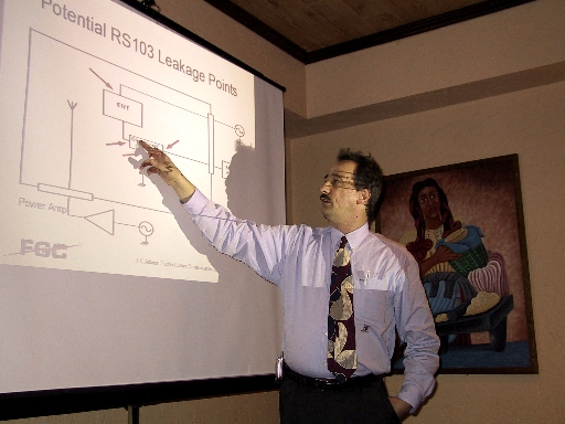
Ray Adams points out potential RF leakage points when conducting RS103 testing to the Phoenix Chapter. Photo by Steve Gerard.
Glenn Gassaway reports that the October 2005 IEEE EMC Phoenix Chapter meeting was held on October 12th at Garcia’s Mexican Restaurant at Rural Road and I-60 in Tempe. This was the first meeting of the fall season, and was very well attended! The meeting began with the customary social hour and dinner from 5 to 7pm. After we all had our fill of Garcia’s wonderful Mexican food, Harry Gaul, our chapter chairman, called the meeting to order at 7:00. Business began with roundtable introductions and the call for EMC employment/employers. Harry mentioned that General Dynamics in Scottsdale is looking for engineers experienced in ionizing radiation effects and Joe Chott mentioned that General Dynamics in Gilbert may soon be looking for experienced EMI design engineers (pending internal search). Harry also discussed potential upcoming speakers. It became apparent that this year will bring a variety of interesting speakers to our chapter! We are also looking forward to a special event in January (more to come). After the general chapter business was completed, Harry introduced our featured speaker, Jim Reed. Jim has worked in 3D EM simulation since 1997 starting with antenna design at TRW Space Park. After TRW, Jim worked with Ansoft in 1998 to support their frequency domain product HFSS. Upon moving back to his home state of Texas in 1999, he developed his own company for 3D EM simulation services, which led to his introduction of CST’s time domain product Microwave Studio. He worked for CST for over 3 years in support, sales and marketing. In May of 2003, Jim returned to promoting his own engineering services for 3D EM simulation with his company Optimal Designs. Jim’s discussion focused on the two initial solution domains used to calculate the electrical properties of a device – frequency domain and time domain. Each domain has advantages and disadvantages which affect the solve time. Jim presented a brief introduction of frequency and time domain calculations with an emphasis on the meshing technique. Several EMC examples were presented using both Ansoft HFSS frequency domain and CST Microwave Studio time domain with consideration to model setup for accuracy and solve time. Jim went through the five basic indicators of when time or frequency domain simulation should be used. Electrically large models often solve faster in time domain. Models with high mesh aspect ratio are generally more suited for frequency domain simulations with tetrahedral mesh. Large bandwidth models should focus on time domain simulations, since a single simulation excites a broad range of frequencies in the time domain. High Q devices should typically use frequency domain simulations, since time domain solutions of these devices may be lengthy due to their energy storage and long decay times. Finally, frequency domain simulations should be used for models with a large number of ports. Jim then presented several examples. The first example used CST’s Microwave Studio (time domain) to solve for the radar cross section of a 10 inch ‘almond’. The second example showed how Ansoft’s HFSS (frequency domain) solved for a small gap. The third example showed how Microwave Studio simulated a blade antenna. This example showed how to establish entry ports and boundary conditions. The fourth example showed how Microwave Studio simulated a cavity resonator (a device with a long decay time). Even with simple geometry, the simulation of this high Q device in the time domain was rather lengthy. The last simulation showed how HFSS simulated a microstrip connector with a complex form factor. The conclusion of the presentation conveyed that both domains are accurate for all passive 3D devices if used properly, but there are clear advantages in solve time and improved accuracy if the proper solution domain is chosen. Jim mentioned that the proper utilization of modeling software was extremely complex and could only be lightly covered in the allotted time given in our chapter meeting. Through his company, Jim provides much more detailed presentations on this subject matter. Jim can be contacted at jim.reed@optimal-designs.com. The chapter thanks Jim for a very interesting presentation indeed. Harry Gaul then called the meeting to a close at about 8:00 pm. Stay tuned to your email for the next meeting announcement, which should be in about a month. Thanks to all who attended!
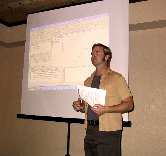
Jim Reed discusses the 5 indicators of when to use frequency domain and when to use time domain EM solvers to the Phoenix Chapter. Photo by Steve Gerard.
The May 2005 IEEE EMC Phoenix Chapter meeting was held at Garcia’s Mexican Restaurant at Rural Road and I-60 in Tempe. This time, the meeting was held on a Wednesday (May 25) as opposed to our usual Thursday night. Our next meeting will be in the fall because our chapter tends to take the long, hot Arizona summers off to enjoy family vacations and escape the heat! After chapter business, Harry Gaul introduced our featured speaker, Prof. Dr. – Ing. Heyno Garbe, a Distinguished Lecturer of the EMC Society. Professor Garbe is currently Dean for Education at the Department of Electrical Engineering and Information Technology at the University of Hannover, Germany. Professor Garbe is very active in several EMC related national and international standardization committees. He is a Senior Member of the IEEE, as well as a member of URSI Com. E, VDE, and the IEEE EMC, AP, IMT and MTT Societies. Since 1997, he has served as chairman of the German chapter of the EMC Society and is currently serving on the Board of Directors of the EMC Society. Professor Garbe started his presentation “Understanding and Avoiding EMC Problems of LANs” by covering the basic fundamentals of attenuation and Near End Cross Talk (NEXT). He spoke of field coupling to several kinds of wire structures, and the effects of common mode to differential mode transformation in balanced versus unbalanced transmission lines. He defined LAN cable structures and their uses including internal shields which tend to reduce wire-to-wire crosstalk, and overbraid shields which reduce field to cable coupling. He also covered digital noise sources that one may encounter in a LAN system. For instance, LAN-emitted digital noise tends to be stochastic and it is important to calculate the power spectral density to ascertain if a noise problem may be evident. Interestingly, Professor Garbe showed a graph which compared the power spectral densities of 10, 100 and 100 base-T Ethernet signals, which showed that 10 base-T signals have the highest amplitude in the lower frequency ranges. If a system tends to be susceptible in the 10 base-T range, then the 10 base-T emitter would be worst-case among the three. The important thing to understand is that the digital encoding affects the potential of susceptibility. Professor Garbe also mentioned the importance of a well terminated cable shield. Terminating a cable shield at one end is not enough. Dr. Garbe showed experimental results indicating that a one-end terminated shield would have the same shielding effectiveness as a completely unshielded cable at higher frequencies where LAN noise is prevalent. He joked that one could save money by simply avoiding all shielding if the design included one-end termination. He also spoke of long pigtail terminations, which are responsible for poor shielding effectiveness. One conclusion that that he drew was that the radiated emissions from LAN cables due to the differential signal is pretty small because of the balanced nature of the signal. The more severe threat is power supply chopper noise which may be present on the LAN wiring. In this case, the power supply noise is common mode so the twisting/balancing provides no reduction. Thus, the shielding of the twisted pairs is necessary to reduce the emissions. Professor Garbe covered the increasingly popular Broadband Power Line Communications Systems, which of course are not shielded. He implied that these are noisy systems indeed. Several questions arose at the end of the talk, including a lively and positive exchange discussing the importance of maintaining a ‘balanced’ design. Stay tuned to your email for the next meeting announcement, which will be after summer Thanks to all who attended! Click HERE to download Dr. Heyno Garbe’s talk on Understanding the EMC Problems of LANs.

Professor Garbe addressed the Phoenix Chapter with a talk entitled “Understanding and Avoiding EMC Problems of LANs”. Photo by Steve Gerard.
Harry Gaul reports that at the April meeting of the Phoenix EMC Chapter, our very own Daryl Gerke gave a well-received talk on “Diagnosing and Troubleshooting EMI Problems”. Daryl began the talk by sharing his philosophy of troubleshooting that he’s refined over many years of being an EMI guru troubleshooter. First, one has to develop an “emergency room” mentality with a fast response because the “patient” is often in pain. The initial information is often confusing or incomplete. And the situation may be tense so one has to keep cool. One must first diagnose and then try fixes because “prescription without diagnosis is malpractice”. Daryl offered up many examples of failures and fixes ranging from ESD to emissions to power disturbances. He also addressed the pros and cons of fixes implemented at the board level versus at the enclosure level. Daryl shared the contents of his magic box of tricks including foil, copper tape, screen, ferrites, and EMI filters. Daryl concluded his talk by emphasizing the need to first diagnose the problem through the gathering and critiquing of data followed by making a plan. The actual fixing of the problem then involves iterating between predicting and monitoring the outcome of fixes.
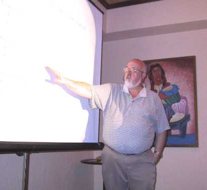
Daryl Gerke explains the critical factors affecting radiated emissions to the Phoenix Chapter in his talk on Diagnosing and Troubleshooting EMI Problems. Photo by Steve Gerard.
Harry Gaul reports that the November 20th meeting included a talk given by David Lee, the Compliance Test Manager for M. Flom Associates in Chandler, AZ. In this talk entitled, Demystifying the Process for Certifying Low Power Transmitters, David Lee focused on the rules and processes for certifying low power transmitters for the FCC, Industry Canada, and the CE Mark (ETSI) requirements.
Dave pointed out that the 47CFR Part 2 contains all of the “gotchas”, ie., the rules and core tests which are then modified by the other parts such as Part 15. He also pointed out that Specific Absorption Rate (SAR) testing often requires performing the tests across all the accessories such as antennas and batteries, and can therefore become quite expensive.
Dave stated that the 47CFR rules are quite intertwined, especially 15.247 for frequency hopping and direct sequence spread spectrum radios. The RS210 document for Industry Canada is roughly equivalent to the FCC Part 15 and Part 18. He also said humorously that the EU is a collection of feudal warring states especially when it comes to the harmonization of frequency bands. Finally, Mr. Lee projected that the FCC rules may incorporate immunity tests in the not-too-distant future.
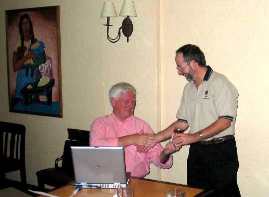
Harry Gaul presents a bottle of Arizona salsa to Mr. David Lee of M. Flom Associates who presented a talk at the November 2004 Phoenix Chapter meeting. Photo by Jim Dykema.
Glen Gassaway reports that once again there was standing room only at the IEEE EMC Phoenix Chapter’s meeting at Garcia’s Mexican Restaurant on Rural Road and I-60 in Tempe. The meeting was held on Thursday, September 30th, and was the kickoff to our new season (since we tend to take the hot Arizona summers off). The meeting began with the customary social hour from 6 to 7pm, which gave all of us time to socialize with friends and past-coworkers that we may have not had time to contact since last spring. After we all had our fill of Garcia’s wonderful food, Harry Gaul, our chapter chairman, called the meeting to order at 7:00. Business began with the call for EMC employment/employers, which went unanswered. It looks like everyone is gainfully employed. Then Harry introduced our infamous Vice chair, Daryl Gerke, who told us of potential future speakers that we may be able to convince to present at our gatherings. Finally, Daryl, introduced our guest speaker, Bill Parker.
Bill Parker began work as an EMC engineer at Genisco Technology Corporation in 1973. After various assignments at Genisco, he started his current EMC consulting business in 1989 and is still going strong. Bill teaches EMC seminars and provides consulting, testing, and teaching services, as well as being very active in the IEEE EMC Society. It was also interesting to hear that Bill is an avid runner, and has even participated in the LA marathon!
Bill’s presentation, entitled “Down Memory Lane; 30 Years of EMI Field Testing” revolved around his vast EMI field testing experiences. He related several “war-stories” including stories of testing in terrible conditions for long hours, on-site tests of engine-generators, motor-generators, uninterruptible power systems, as well as testing portions of larger equipment, such as a Navy submarine, and even the Space Shuttle Challenger! He took us ‘down memory lane’ by showing us photos of older EMI test equipment, bringing back the good old days for us old-timers. He told us of his exploits in his test equipment van and how to be fully-equipped for an upcoming field test. Bill had too many stories to list in this article, which could never do them justice – you just have to hear them for yourself!
Bill concluded his presentation with a discussion of significant lessons learned throughout the years, for example: using a flashlight, headphones, and a cheap AM/FM radio on a stick as a diagnostic tool for evaluating chamber shielding effectiveness.
Harry then called the meeting to a close at about 9:00 pm. Stay tuned to your email for the next meeting announcement. Thanks to all who attended!
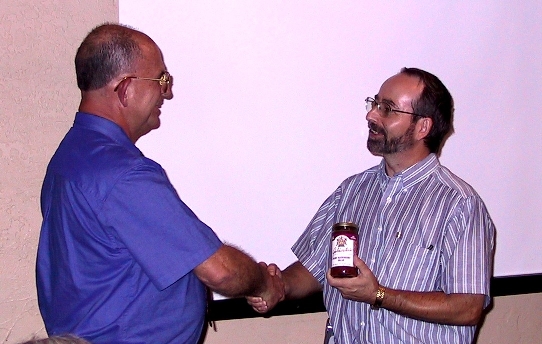
After Bill Parker’s presentation, Harry Gaul awards him the traditional jar of Arizona salsa as a hearty thank-you for his entertaining presentation! Photo by Steve Gerard
Glen Gassaway reports that Garcia’s Mexican Restaurant had another packed house at our April 22nd IEEE EMC Society Phoenix Chapter meeting. After a lively social hour (where the drinks were on TMS’s tab – thanks Brent!), Harry Gaul was finally able to calm everyone down and get to business. Harry reviewed a schedule of upcoming meetings, including inviting Bill Parker in the fall for a thorough review of EMC ‘war stories’. Daryl Gerke may also be an upcoming presenter (stay tuned). Finally, the chapter intends to host a ½ day colloquium on antennas in January. There’s more to come, too! Possibly in light of a strengthening economy, the standard call for EMC employment went unanswered – does that mean everyone is gainfully employed??. Harry then introduced our featured presenter, David Seabury, a Senior Business Development Manager with ETS-Lindgren. David began his presentation, entitled: “A Review of Radio Frequency Exposure Requirements of FCC OET65 and the Latest Direction of the IEEE/IEC Standards”. David explained that there are two predominant RF exposure mechanisms that have enforceable standards in the US, including “Maximum Permissible Exposure” (MPE) and “Specific Absorption Rate” (SAR). The FCC’s Office of Engineering and Technology (OET) Guidelines described in OET-65 Ed 97-01 addresses both mechanisms. MPE typically refers to the operation of RF-emitting devices in the far field (>20cm distances) whereas SAR applies to devices within 20cm of the body. MPE also allows either measured or predicted assessments, whereas SAR almost always requires measured assessments. Control methodologies for MPE involve a variety of options, including limiting output power, time averaging, shielding, antenna pattern management, or (the most popular) implementing personnel access restrictions, including adding signs or fences. Enforcement of MPE standards is increasing, with more actions and on-site reviews taking place. In addition to the FCC, OSHA also enforces MPE limits, focusing on the workplace. OSHA has by and large adopted the OET-65 limits, but also addresses induced currents and covers a lower frequency range. Key websites include: www.fcc.gov/oet/rfsafety www.osha.gov/SLTC/radiofrequencyradiation In the United States, SAR regulations are covered by FCC OET supplement C 01-01. It indicates the applicability of the 20cm rule – where the fixed, mobile or portable device has to be operated within 20cm of a human for the rules to apply. Europe’s near equivalent standard is EN50630/50631 and most countries use the self-certification method of compliance. Test methodologies for SAR include setting the device under test at the highest RF power and probing localized temperature rises in a ‘liquid’ phantom (head) or box (body). A signal generator and coupler are typically used for pretest calibration checks and the tests are normally done in an automated fashion, using a robotic arm for probe positioning. The talk concluded with an update of the work being performed in the standards committees and the potential impact to the FCC’s requirements.
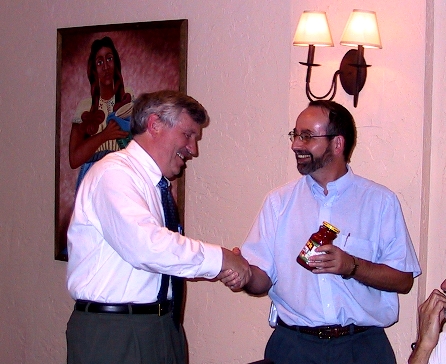
After David Seabury’s presentation, Harry Gaul awarded him the customary jar of salsa. Thanks to David for your informative presentation! Photo by Steve Gerard.
Harry Gaul reports that we had an exciting time at the February 19th IEEE EMC Society Phoenix Chapter meeting held at the Marriott Mountain Shadows in Scottsdale. This was a joint meeting held in conjunction with the EMC Society’s Board of Directors’ meeting. The attendees enjoyed some wonderful hors d’oeuvres and drinks by the pool prior to the presentation on reverberation chambers by Mike Hatfield of the Naval Surface Warfare Center Dahlgren Division. Mike spoke on “How To Conduct Electromagnetic Effects Testing Using a Microwave Oven and a Pair of Dice, Or, A Statistical Approach For Conducting System Electromagnetic Vulnerability Assessments.” Mike began his talk with a short history of actual devastating HERO problems in the Navy followed by an in-depth look at the statistical basis for repeatability in mode-tuned chambers as a function of the number of tuner positions. The premise of Mike’s talk was that large uncertainties in the test process would lead to inconclusive statistical results for the safety of ordnance systems. He contrasted the typical anechoic chamber test method which tends to have too few of aspect angles versus mode-stirred chambers where the directivity tends to get washed out. Mike made the comment that the peak of the mode-stirred responses will equate to the average of the anechoic chamber responses given a sufficient number of tuner positions in the reverberation chamber and aspect angles in an anechoic chamber. Mike provided some interesting test results for measuring the shielding effectiveness of boxes. As it turned out, the anechoic chamber results were much more uniform when a mechanical stirrer was placed inside the box. The test results obtained in reverberation chambers were amazingly repeatable across multiple test labs. A lively discussion ensued at the end of the presentation concerning stirring as opposed to stepping the tuner and the loss of statistical significance because of the response time of the unit under test. 
Mike Hatfield of the Naval Surface Warfare Center Dahlgren Division explains the importance of performing electromagnetic testing with predictable uncertainties. Photo by Steve Gerard.
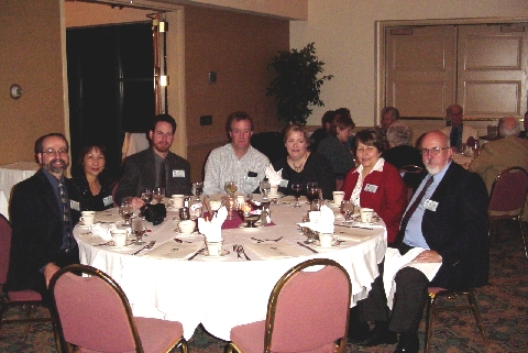
The Phoenix EMC Chapter and their spouses attended the Phoenix IEEE Section’s Annual Awards Banquet where vice-chairperson, Daryl Gerke, won a technical achievement award for his presentation on the “Mysteries of Grounding”. From left are Harry and Lo-An Gaul, Steve Gerard, Terry and Suzie Donohoe, and Mary and Daryl Gerke. Photo by Steve Gerard.